Flexible automatic assembling mechanism and method for automobile driving motor

A driving motor and automatic assembly technology, which is applied in the manufacture of motor generators, electromechanical devices, electrical components, etc., can solve the problems that the assembly quality of the motor cannot be guaranteed, the assembly quality cannot be guaranteed, and the shaft of the rotor assembly is not fixed. Achieve the effects of improving assembly quality, accurate and reliable positioning, and good coaxiality

Pending Publication Date: 2022-01-04
智新科技股份有限公司
View PDF0 Cites 0 Cited by
  • Summary
  • Abstract
  • Description
  • Claims
  • Application Information

AI Technical Summary

Problems solved by technology

[0002] At present, the single-motor stator and rotor assembly method is as follows: first, the rear end cover rotary chamber in the stator and end cover assembly is used as the center positioning, and then it is axially fixed, and then the rotor is clamped by three claws and the top form. The stator and rotor are assembled by moving the rotor up and down. This assembly method can only be fixed at one end of the rotor shaft. Because the permanent magnet of the stator has strong magnetism, it will cause the stator and rotor to absorb and scratch, and the rotor shaft head bears the leverage force, which cannot be achieved. Guarantee the quality of motor assembly
[0003] In addition, the current mainstream two-in-one drive motor is usually combined

Method used


Image

  • Flexible automatic assembling mechanism and method for automobile driving motor
  • Flexible automatic assembling mechanism and method for automobile driving motor
  • Flexible automatic assembling mechanism and method for automobile driving motor

Examples


Embodiment Construction

[0031] The specific embodiments of the present invention will be further described below in conjunction with the accompanying drawings. It should be noted here that the descriptions of these embodiments are used to help understand the present invention, but are not intended to limit the present invention.

[0032] In addition, it should be noted that the words "front", "rear", "left", "right", "top", "bottom", "upper" and "lower" used in the following description refer to the The terms "inner" and "outer" refer to directions toward or away from, respectively, the geometric center of a particular component.

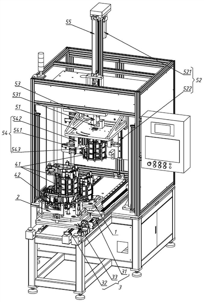
[0033] like figure 1As shown, a flexible automatic assembly mechanism for automobile drive motors in the present invention includes a stator positioning tool 1, a rotor positioning tool 2, a tool moving mechanism 3 and a combined motor mechanism. The stator positioning tool 1 is used to place the stator assembly 41, and The stator assembly 41 is positioned in the circumf...


PUM


Abstract

The invention discloses a flexible automatic assembling mechanism and method for an automobile driving motor. The assembling mechanism comprises a stator positioning tool used for placing a stator assembly, a rotor positioning tool used for placing a rotor assembly, a tool moving mechanism used for moving the stator positioning tool and the rotor positioning tool to an assembling station, and an assembling motor mechanism. The assembling motor mechanism comprises a pressing plate, a stator moving mechanism used for driving the pressing plate to reciprocate in the axial direction of an assembling motor and a guide rod, the pressing plate is arranged at the top of the assembling station, a stator clamping mechanism used for clamping and fixing a stator assembling part is arranged on the bottom face of the pressing plate, and the guide rod penetrates through the pressing plate in a sliding mode and can stretch out and draw back to adjust the length. When the stator and the rotor are assembled, the guide rod is extended to be coaxially fixed with the rotating shaft of the rotor assembly, so that the rotating shaft is kept not to shake, movement of the pressing plate and the stator assembly can be guided, adsorption scraping in the stator and rotor assembling process is effectively avoided, and the assembling quality is improved.

Description

technical field [0001] The invention relates to the technical field of motor assembly, in particular to a flexible automatic assembly mechanism and method for an automobile drive motor. Background technique [0002] At present, the single-motor stator and rotor assembly method is as follows: first, the rear end cover rotary chamber in the stator and end cover assembly is used as the center positioning, and then it is axially fixed, and then the rotor is clamped by three claws and the top form. The stator and rotor are assembled by moving the rotor up and down. This assembly method can only be fixed at one end of the rotor shaft. Because the permanent magnet of the stator has strong magnetism, it will cause the stator and rotor to absorb and scratch, and the rotor shaft head bears the leverage force, which cannot be achieved. Guarantee the quality of motor assembly. [0003] In addition, the current mainstream two-in-one drive motor is usually combined with the rotor and the...

Claims


Application Information

Patent Timeline
IPC IPC(8): H02K15/00H02K15/02H02K15/03
CPCH02K15/00H02K15/02H02K15/03Y02T10/64
Inventor 李荡李维虎章毅康超彭勃谢守祥吴晶灵杨兵张帅
Owner 智新科技股份有限公司
Why Eureka
Try Eureka