3d display device and 3d display method

A display device and display unit technology, applied in static indicators, optics, instruments, etc., can solve problems such as image quality degradation, and achieve the effect of improving image quality and smooth video images

Inactive Publication Date: 2012-05-30
SONY CORP
View PDF11 Cites 3 Cited by
  • Summary
  • Abstract
  • Description
  • Claims
  • Application Information

AI Technical Summary

Problems solved by technology

As a result, image quality may degrade

Method used


Image

  • 3d display device and 3d display method
  • 3d display device and 3d display method
  • 3d display device and 3d display method

Examples


no. 2 approach

[0049]

[0050] [Construction Example]

[0051] (overall construction example)

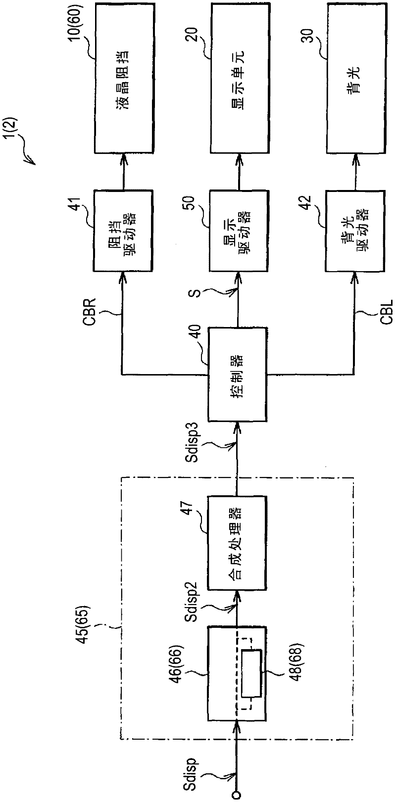
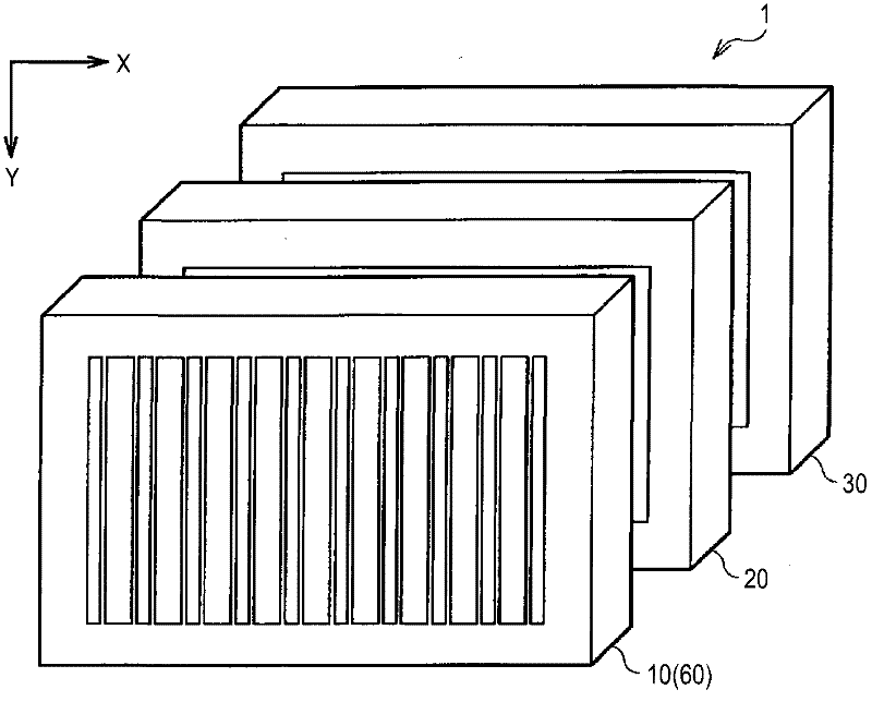
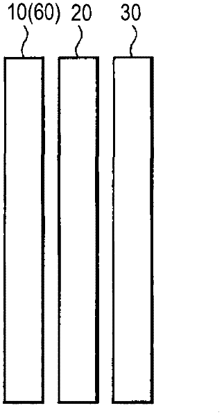
[0052] figure 1 A configuration example of a 3D display device according to an embodiment of the present disclosure is shown. The 3D display method according to the embodiment of the present disclosure is realized by the present embodiment, and will be described here. The 3D display device 1 includes a composite image generator 45 , a controller 40 , a display driver 50 , a display unit 20 , a backlight driver 42 , a backlight 30 , a barrier driver 41 and a liquid crystal barrier 10 .

[0053] The composite image generator 45 generates a video signal Sdisp3 based on a video signal Sdisp supplied from the outside. The composite image generator 45 includes an interpolation processor 46 including an interpolation image generator 48 and a composite processor 47 . As will be described below, the interpolation processor 46 has a function of, when the 3D display apparatus 1 displays a 3D video imag...


PUM


Abstract

The invention relates to a 3D display device and a 3D display method. The display device includes: an optical barrier unit which includes a plurality of gate groups each including a plurality of gates, and in which gates in different groups perform a gating operation individually at different timings; a combined image generator which generates a plurality of sequences of combined images each corresponding to the plurality of gate groups based on a plurality of different viewpoint images in accordance with an opening timing of the respective gate groups; and a display unit which displays the corresponding sequence of combined images in synchronization with the gating operation of the respective gate groups, wherein the combined image generator generates at least one sequence of combined images through interpolation.

Description

technical field [0001] The present invention relates to a parallax barrier 3D display device and a method capable of performing 3D display. Background technique [0002] In recent years, display devices capable of 3D display (3D display devices) have attracted attention. The 3D display displays left-eye video images and right-eye video images with parallax (different viewpoints), thereby allowing viewers to recognize them as 3D videos with a sense of depth when viewing the respective video images with their right and left eyes image. In addition, display devices capable of presenting more natural 3D video images to viewers by displaying three or more video images with parallax are also being developed. [0003] Such 3D display devices are roughly classified into those that require and do not require dedicated glasses. Dedicated glasses are uncomfortable for the viewer, so a device that does not require dedicated glasses is desirable. Examples of display devices that do n...

Claims


Application Information

Patent Timeline
IPC IPC(8): H04N13/00G09G3/36
CPCH04N13/0454G02B27/22H04N13/0486H04N13/0409H04N13/0029H04N13/31H04N13/315H04N13/359H04N13/139
Inventor 佐藤能久冈本好喜吉田哲之千叶淳弘坂本祥
Owner SONY CORP
Why Eureka
Try Eureka