Vehicle motion control device

A motion control device and vehicle technology, applied in braking control systems, vehicle components, transportation and packaging, etc., can solve problems such as discomfort, understeer, and reduced mitigation effects, and achieve a less discomfort and improved safety performance. Effect

Active Publication Date: 2012-05-30
HITACHI ASTEMO LTD
View PDF9 Cites 59 Cited by
  • Summary
  • Abstract
  • Description
  • Claims
  • Application Information

AI Technical Summary

Problems solved by technology

As a result, not only the reduction effect of understeer is reduced, but also discomfort will be generated due to the need for more than deceleration.

Method used


Image

  • Vehicle motion control device
  • Vehicle motion control device
  • Vehicle motion control device

Examples


Embodiment Construction

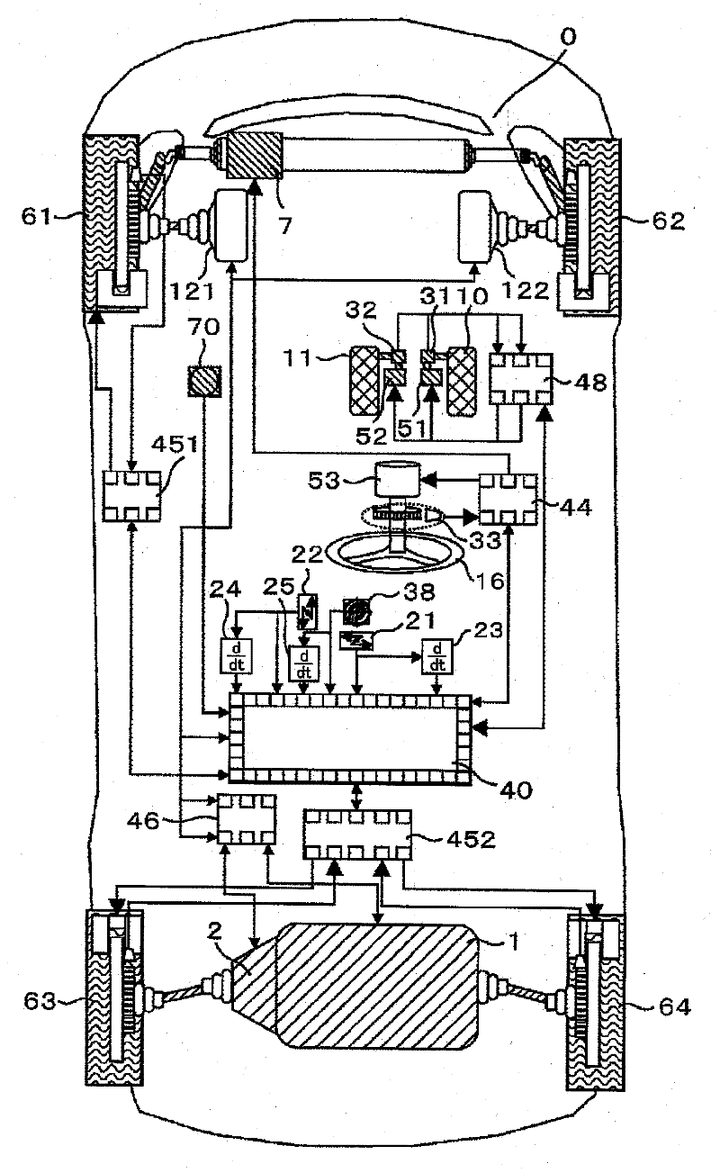
[0078] figure 1 An overall configuration of one embodiment of the motion control device for a vehicle according to the present invention is shown.

[0079] In this embodiment, the vehicle 0 is configured by a so-called by wire system, and there is no mechanical coupling between the driver and the steering mechanism, acceleration mechanism, and deceleration mechanism.

[0080]

[0081] Vehicle 0 is a four-wheel-drive vehicle ( A ll W heel D rive: AWD car). Connected to the engine 1 is attached a driving force distribution mechanism 2 capable of freely distributing engine torque to left and right wheels. Here, the difference regarding the power source of an electric motor, an internal combustion engine, etc. is not closely related to the present invention. As the most suitable example shown in the present invention, it is configured to be able to freely control the driving force and braking force of the four wheels by combining with the four-wheel independent braking desc...


PUM


Abstract

Provided is a vehicle motion control device which enables a reduction in uncomfortable feeling and an improvement in safety. Specifically provided is a vehicle motion control device capable of independently controlling the driving forces and braking forces of four wheels, said vehicle motion control device comprising a first mode (G-Vectoring control) in which approximately the same driving force and braking force are generated in right and left wheels among the four wheels on the basis of a forward/backward acceleration/deceleration control command linked with the lateral motion of a vehicle, and a second mode (sideslip prevention control) in which different driving forces and braking forces are generated in the right and left wheels among the four wheels on the basis of a target yaw moment calculated from sideslip information relating to the vehicle, wherein the first mode is selected when the target yaw moment is a predetermined threshold value or less, and the second mode is selected when the target yaw moment is greater than the threshold value.

Description

technical field [0001] The present invention relates to a motion control device for a vehicle capable of controlling the driving force and control force of four wheels. Background technique [0002] A command value for automatically performing acceleration and deceleration linked to a steering wheel operation is shown in Patent Document 1 ((numeral 1)), for example. [0003] [number 1] [0004] G xc = - sgn ( G y · G · y ) C xy 1 + Ts | G · y | + G x _ DC ...(Numb...

Claims


Application Information

Patent Timeline
Patent Type & Authority Applications(China)
IPC IPC(8): B60W30/02B60W10/08B60W10/18B60T8/1755B60W10/12B60W10/188B60W10/192B60W30/00B60W40/101B60W40/103B60W40/107B60W40/114
CPCB60W2720/30B60W10/04B60W10/119B60T8/1755B60W10/08B60W30/045B60W10/184B60W10/18B60W2720/14B60T2270/302B60W30/18145
Inventor 山门诚斋藤真二郎横山笃高桥绚也吉田龙也
Owner HITACHI ASTEMO LTD
Why Eureka
Try Eureka