Micro-sensing clamping device

A clamping device and clamping technology, applied in the direction of chuck, micro manipulator, manipulator, etc., to achieve the effect of high practicability and improving the degree of intelligence

Inactive Publication Date: 2012-06-06
METAL INDS RES & DEV CENT
View PDF9 Cites 10 Cited by
  • Summary
  • Abstract
  • Description
  • Claims
  • Application Information

AI Technical Summary

Problems solved by technology

[0021] The micro-gripper proposed in this patent can monitor the clamping state through the micro-force sensor module in the structure, which can ensure reliable clamping and will not damage the workpiece due to excessive clamping force, but does not involve clamping micron Viscous problems that may occur with components

Method used


Image

  • Micro-sensing clamping device
  • Micro-sensing clamping device
  • Micro-sensing clamping device

Examples


Embodiment Construction

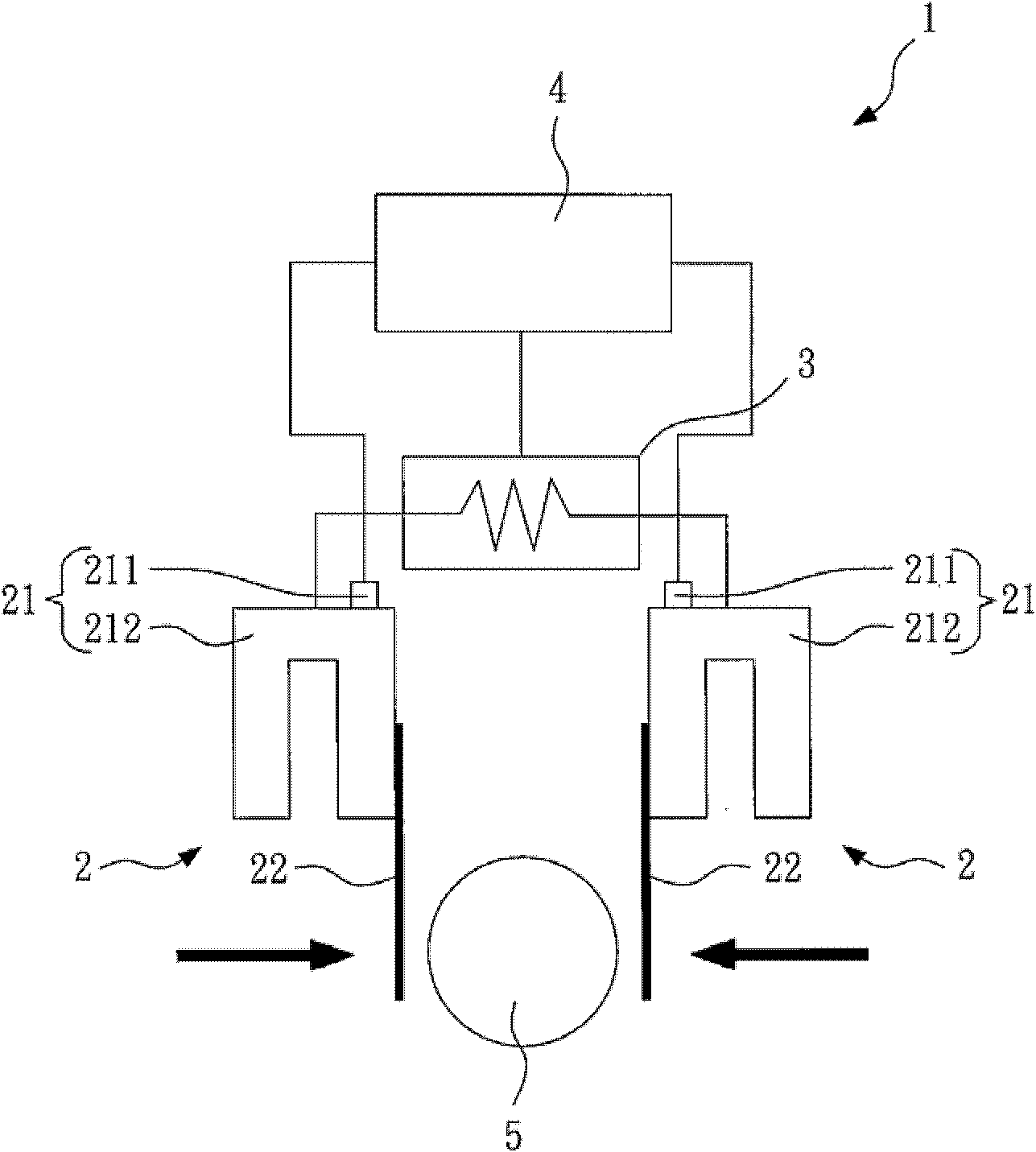
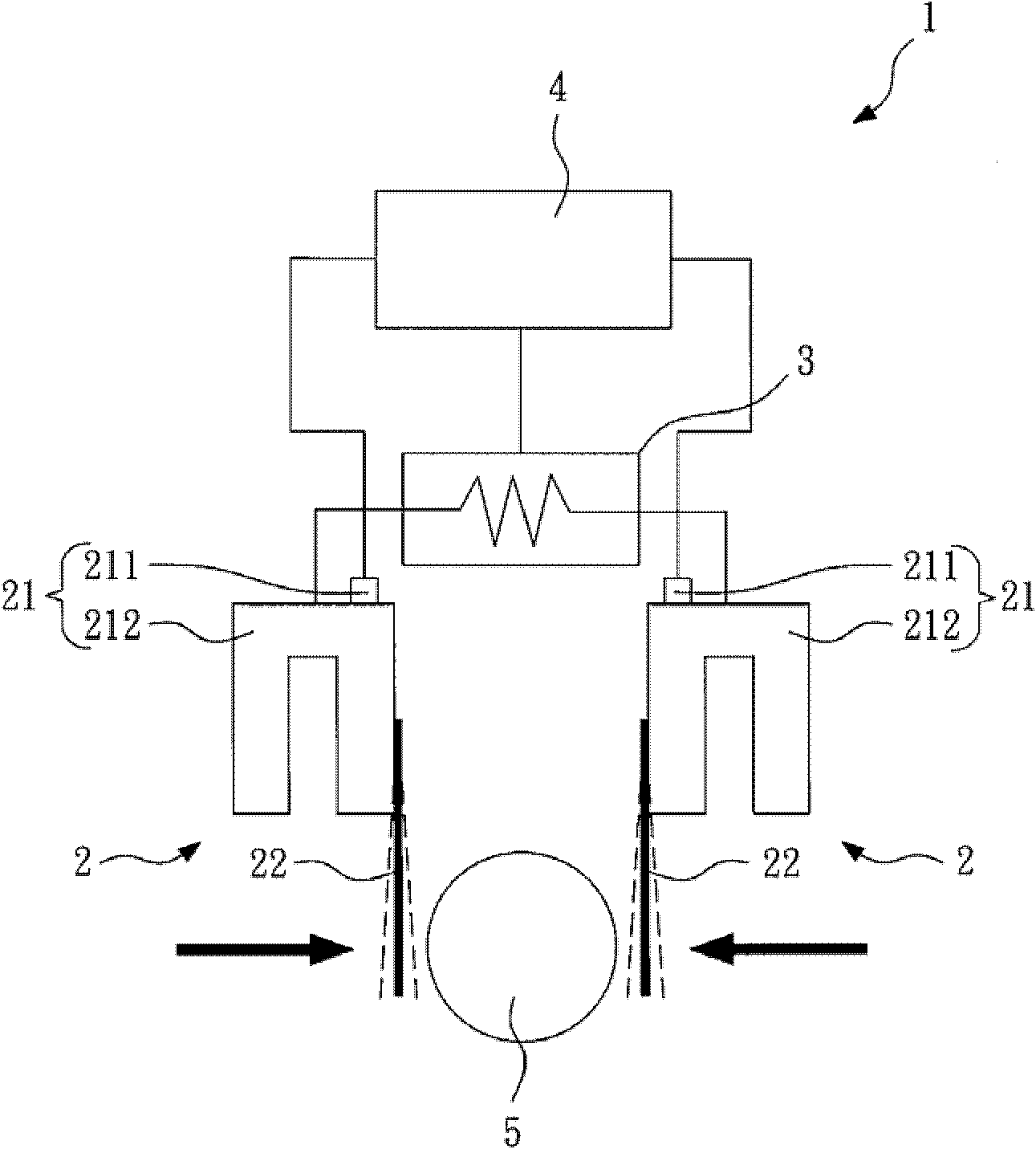
[0040] figure 1 A schematic diagram showing the micro-sensing clamping device of the present invention. The micro-sensing clamping device 1 of the present invention includes two clamping units 2 , a moving unit 3 and a control unit 4 . At least one of the two clamping units 2 includes an oscillating device 21 for generating oscillation.

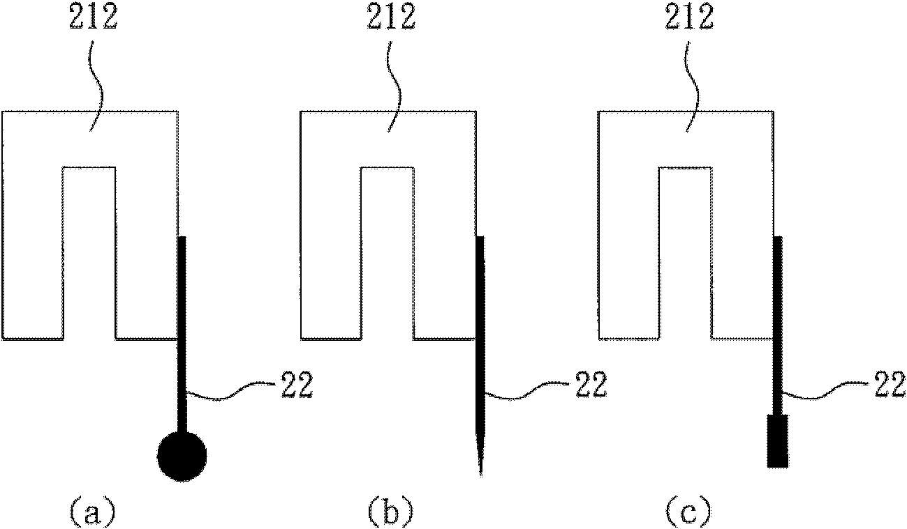
[0041] In this embodiment, each clamping unit 2 includes one oscillating device 21 , and each clamping unit 2 further includes a clamping arm 22 . The ends of these clamping arms 22 can be an enlarged portion, such as spherical or rectangular (such as figure 2 a, 2c shown), alternatively, the ends of these clamping arms 22 can be a narrowing portion, such as a pointed cone (such as figure 2 shown in b).

[0042] In this embodiment, each oscillating device 21 includes an oscillating source 211 and a tuning fork element 212 . The oscillation source 211 can generate an oscillation with a fixed frequency, and the tuning fork element 212 ge...


PUM


Abstract

The invention discloses a micro-sensing clamping device comprising two clamping units. At least one of the clamping units comprises a vibration device, which can be used to generate the vibration. A control unit is connected with the clamping units and a movable unit, and can be used to control the vibration generation of the vibration device and monitor the change of the vibration frequency / amplitude of the vibration device, and also can be used to control the movable unit to moving the clamping units in order to clamp, hole or loosen the clamp object according to the change of the vibration frequency / amplitude of the vibration device. Thereby the intelligent degree of the clamping can be improved, the delay or attachment problem of the object to be clamped can be overcome, the accurate control pick-up and put-away can be achived, the high practicability can be realized, and the problems capable of leading to the damage or slip-off of the object to be clamped can be overcome.

Description

technical field [0001] The present invention relates to a clamping device, in particular, to a micro-sensing clamping device. Background technique [0002] In the field of existing micro fixtures, the micro strain gauge clamping device manufactured by the semiconductor manufacturing process is used as the clamping structure, and the sensing ability comes from the deformation detection of the strain gauge during the clamping process. However, the clamping principle of this conventional fixture has a shortcoming that is difficult to overcome when dealing with micron-scale components. It is difficult to avoid the viscous force between the tiny components, and it is easy to cause the micron components to stick during the process of clamping relaxation. Stagnated on the clamp arm, causing difficulty in clamping and taking out. [0003] The following is the prior art literature on micro grippers. [0004] Prior art document 1 (clamping device, China Taiwan Patent Publication No....

Claims


Application Information

Patent Timeline
Patent Type & Authority Applications(China)
IPC IPC(8): B25J7/00B25J15/00
Inventor 刘彦志安乃骏颜圣展陈世陆
Owner METAL INDS RES & DEV CENT
Why Eureka
Try Eureka