Umbrella device

An umbrella pole and umbrella cloth technology, applied in umbrellas, clothing, walking sticks, etc., can solve problems such as inconvenience for users, inconvenience for users and others

Inactive Publication Date: 2012-06-13
株式会社世普劳统
View PDF0 Cites 8 Cited by
  • Summary
  • Abstract
  • Description
  • Claims
  • Application Information

AI Technical Summary

Problems solved by technology

That is to say, the umbrella holder cannot close the umbrella after fully entering the car, and the umbrella holder's body part has to be exposed to the outside of the car door to fold the umbrella. Like this, when the umbrella is closed, the user will inevitably Exposure to rainwater, causing inconvenience to users
[0004] In add

Method used


Image

  • Umbrella device
  • Umbrella device
  • Umbrella device

Examples


Embodiment Construction

[0125] Hereinafter, embodiments of the umbrella device 1 of the present invention will be described in detail with reference to the drawings.

[0126] [The overall structure of the umbrella device]

[0127] First, the overall structure and main components of the umbrella device 1 will be described in detail.

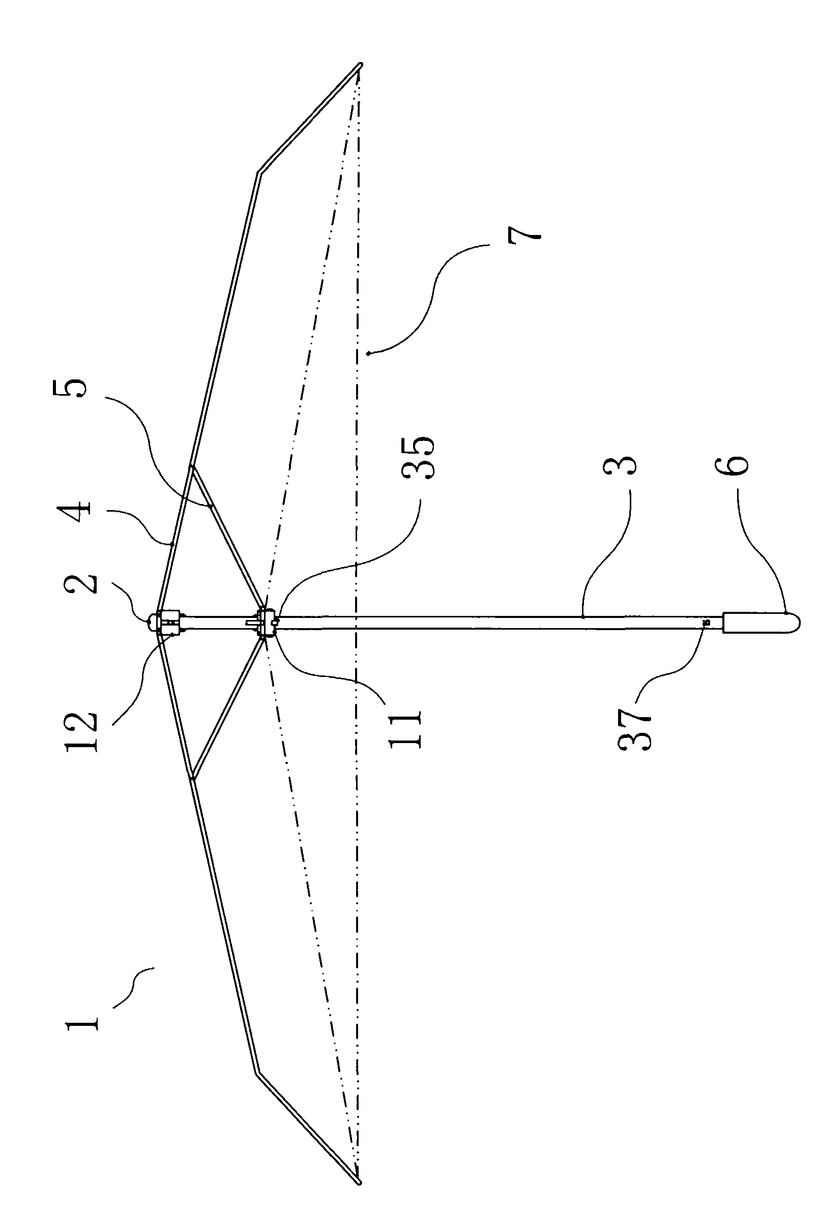
[0128] figure 1 It is a schematic diagram of the expanded state of the umbrella device 1 according to one embodiment of the present invention.

[0129] Such as figure 1 As shown, the umbrella device 1 of one embodiment of the present invention includes: an umbrella pole 3, an umbrella cap 2 positioned at the top end of the umbrella pole 3, an umbrella handle 6 positioned at the bottom end of the umbrella pole 3, a first slide mounted on the umbrella pole 3 The block 11 and the second slider 12, the long bone 4 connected to the second slider 12, the strut 5 connected to the first slider 11, and the umbrella cloth 7.

[0130] In this embodiment, for example, the umbrel...


PUM


Abstract

The invention relates to a reversely openable umbrella device (1), which comprises an umbrella rod (3) of which the top end is connected with an umbrella cap (2), a first sliding block (11) which is arranged on the umbrella rod (3) in a freely sliding manner, a second sliding block (12) which is arranged on the umbrella rod (3) in a freely sliding manner and between the first sliding block (11) and the umbrella cap (2) and is connected with the first sliding block (11), umbrella cloth (7) which forms the umbrella surface of the umbrella device (1) when the umbrella device (1) is opened, a long bone (4) of which one end is connected with the second sliding block (12) and which serves as a frame for supporting the umbrella cloth (7) when the umbrella device (1) is opened, and a supporting bone (5) of which one end is connected with the first sliding block (11) and of which the other end is connected with the long bone (4) to drive the long bone (4) to move. The umbrella device (1) can be reversely opened and closed.

Description

technical field [0001] The present invention relates to an umbrella device, in particular to an umbrella device that can be opened and closed reversely. Background technique [0002] In the prior art, umbrellas generally have a plurality of long bones used to support the umbrella surface. There are movable parts in the middle of each long bone. The bar slides freely on the slider. However, whether it is a straight umbrella or a folding umbrella, when closing, the slider is moved toward the handle of the umbrella, and the brace is pulled to drive the movement of the long bones, so that the free ends of the long bones are drawn toward the handle of the umbrella, thereby closing the umbrella. Conversely, the umbrella can be opened if the slider is moved upwards. [0003] However, when closing the umbrella with the above structure, since the direction of movement of the free ends of the long bones points to the user, some inconvenience will be brought to the user. For example...

Claims


Application Information

Patent Timeline
IPC IPC(8): A45B25/14
CPCA45B19/00A45B25/06A45B25/14A45B2019/008
Inventor 田中哲郎
Owner 株式会社世普劳统
Why Eureka
Try Eureka