Disc brake structure

A disc brake and brake body technology, applied in the direction of brake type, hoisting device, mechanical equipment, etc., can solve the problems of easy fatigue, brake failure, poor intelligence, etc., and achieve improved intelligence effect, uniform braking force, The effect of simple structure

Inactive Publication Date: 2012-06-13
江苏华商企业管理咨询服务有限公司
View PDF0 Cites 4 Cited by
  • Summary
  • Abstract
  • Description
  • Claims
  • Application Information

AI Technical Summary

Problems solved by technology

[0002] Disc brakes are widely used in deceleration braking and parking of mine hoists, large traction winches, and hoisting and transporting machinery; and emergency braking under safety conditions. At present, disc brakes used in the above fields have a structural There are relatively complex and high failure rate defects. At the same time, due to structural reasons, the braking force of this type of brake is provided by the brake spring. During the process of releasing the brake, the hydraulic cylinder pushes the piston. , Compress the brake spring to achieve the purpose of releasing the brake. Because the brake spring is used for a long time, it is prone to fatigue and damage; therefore, it is easy to reduce the braking effect, and even brake failure will occur, resulting in safety accidents In addition, this kind of brake has the defect of poor intelligence because it cannot monitor the braking and release status

Method used


Image

  • Disc brake structure
  • Disc brake structure

Examples


Embodiment Construction

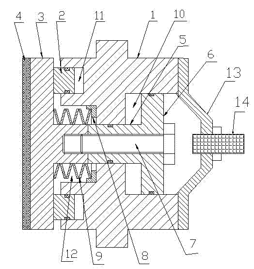
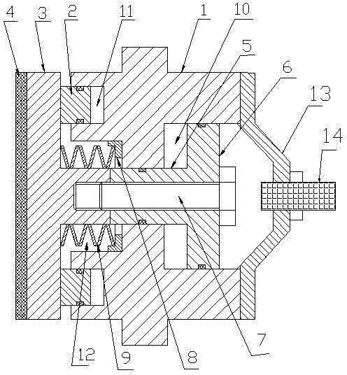
[0009] The relief cylinder 10 and the spring chamber 11 are arranged at both ends of the cylinder body 1 respectively, there is a through hole communicating between the relief cylinder 10 and the spring chamber 11, and the brake cylinder 11 is arranged on the end face of the cylinder body 1 at the same end as the spring chamber 12. The section of the moving cylinder 11 is in the shape of a ring, the piston 6 is installed in the relief cylinder 10, the guide rod 5 passes through the middle hole of the spring chamber 12 and the relief cylinder 10, and one end of the guide rod 5 is connected and fixed with the piston 6, The fastening bolt 7 passes through the piston 6 and the guide rod 5 in turn and is connected and fixed with the brake body 3. A spring seat 8 is installed in the spring chamber 12, and a butterfly spring 9 is installed on the spring seat 8. The butterfly spring 9 is used for the brake. The body 3 forms a compressed state, and an annular piston 2 is installed in th...


PUM


Abstract

The utility model discloses a disc brake structure, which belongs to the technical field of disc brakes. A releasing cylinder and a spring chamber are respectively arranged at two ends of a cylinder body; a braking cylinder is arranged on the end surface of the cylinder body at one end where the spring chamber is also arranged; a piston is installed in the releasing cylinder; a guide rod penetrates through middle holes of the spring chamber and the releasing cylinder; one end of the guide rod is connected with the piston; a fastening bolt penetrates through the piston and the guide rod in sequence and then is connected and fixed with a brake body into a whole body; a spring seat is installed in the spring chamber; a belleville spring is installed on the spring seat; the belleville spring compresses the brake body; an annular piston is installed in the braking cylinder; a friction disk is fixed at the outer end of the brake body; a fixing bracket is installed at the end part of the cylinder body; and a magnetic induction type sensor is installed at the center of the bracket. The disc brake structure has the advantages of simple structure, reliability in operation and intellectualization.

Description

technical field [0001] The invention relates to a disc brake structure, belonging to the technical field of disc brake structures. Background technique [0002] Disc brakes are widely used in deceleration braking and parking of mine hoists, large traction winches, and hoisting and transporting machinery; and emergency braking under safety conditions. At present, disc brakes used in the above fields have a structural There are relatively complex and high failure rate defects. At the same time, due to structural reasons, the braking force of this type of brake is provided by the brake spring. During the process of releasing the brake, the hydraulic cylinder pushes the piston. , Compress the brake spring to achieve the purpose of releasing the brake. Because the brake spring is used for a long time, it is prone to fatigue and damage; therefore, it is easy to reduce the braking effect, and even brake failure will occur, resulting in safety accidents In addition, this kind of br...

Claims


Application Information

Patent Timeline
Patent Type & Authority Applications(China)
IPC IPC(8): B66D5/14B66D5/26F16D66/00
Inventor 孟庆才周丽
Owner 江苏华商企业管理咨询服务有限公司
Why Eureka
Try Eureka