Display control and monitoring components and display systems

A display control and display system technology, applied to static indicators, instruments, data exchange through path configuration, etc., can solve the problems that the receiving card load cannot be maximized, and the wiring is complicated, so as to save quantity, improve utilization rate, and simplify The effect of connecting lines

Active Publication Date: 2016-09-07
XIAN NOVASTAR TECH
View PDF5 Cites 1 Cited by
  • Summary
  • Abstract
  • Description
  • Claims
  • Application Information

AI Technical Summary

Problems solved by technology

[0006] However, in the prior art, the loading of the receiving card cannot be maximized, and a receiving card is required on each LED light box; in addition, all monitoring information needs to be aggregated to the sending card through the receiving card, resulting in complicated wiring

Method used


Image

  • Display control and monitoring components and display systems
  • Display control and monitoring components and display systems
  • Display control and monitoring components and display systems

Examples


no. 1 example

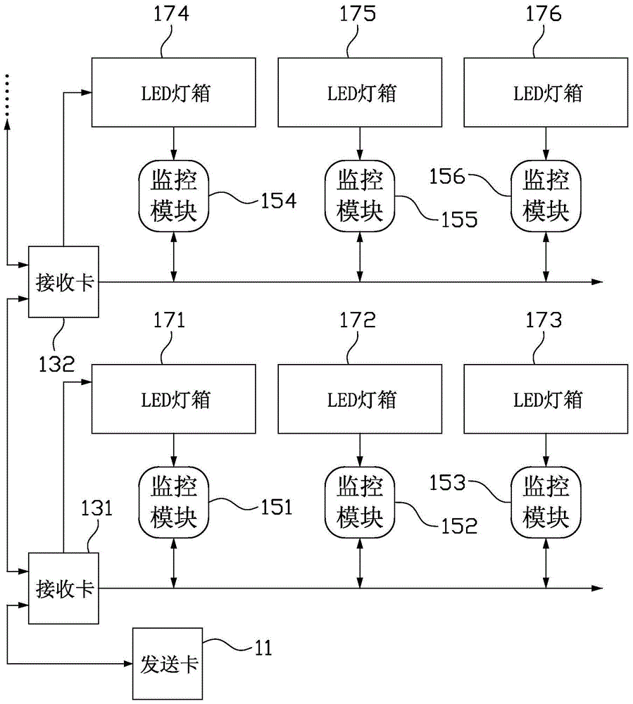
[0028] figure 2 It is a schematic structural diagram of the LED display system according to the first embodiment of the present invention. like figure 2 As shown, the LED display system includes a display control and monitoring component and a plurality of display modules such as LED light boxes 171, 172, 173, 174, 175, 176; the display control and monitoring component includes a sending card 11, a plurality of receiving cards 131, 132 and a plurality of monitoring modules 151, 152, 153, 154, 155, 156.

[0029] Wherein, receiving card 131,132 is as a kind of display control card, and it is for example connected sending card 11 in cascade mode by network cable, that is, receiving card 131 is connected sending card 11, and receiving card 132 is connected sending card 11 by receiving card 131; The card 11 acquires video source signals (such as DVI signals) from the host computer and generates video image data after proper processing, which is provided to the receiving cards 13...

no. 2 example

[0034] Figure 4 It is a schematic diagram of the structure of the LED display system according to the second embodiment of the present invention. like Figure 4 As shown, the LED display system includes a display control and monitoring component and a plurality of display modules such as LED light boxes 171, 172, 173, 174, 175, 176; the display control and monitoring component includes a sending card 11, a plurality of receiving cards 231, 232, and a plurality of monitoring modules 251, 252, 253, 254, 255, 256.

[0035] Wherein, the receiving card 231,232 is a kind of display control card, which is connected to the sending card 11 in a cascaded manner, for example, through a network cable, that is, the receiving card 231 is connected to the sending card 11, and the receiving card 232 is connected to the sending card 11 through the receiving card 231; The card 11 acquires video source signals (such as DVI signals) from the host computer and generates video image data after pr...


PUM


Abstract

The invention relates to a display control and monitoring component and a display system using the display control and monitoring component. Wherein, the display control and monitoring component is used to cooperate with a plurality of display modules, and the plurality of display modules include a first display module and a second display module. The display control and monitoring component includes a display control card, a first monitoring module and a second monitoring module, the first monitoring module and the second monitoring module are respectively used to connect the first display module and the second Two display modules, the display control card is used to provide display driving signals to the first display module and the second display module connected to it in cascade, and the first monitoring module and the The second monitoring module is connected to the display control card through a bus. Therefore, the present invention can solve the problems in the prior art that the loading of the receiving card cannot be maximized and the wiring is complicated.

Description

technical field [0001] The invention relates to the technical field of display control, in particular to a display control and monitoring component and a display system. Background technique [0002] LED (Light Emitting Diode, Light Emitting Diode) display technology, as a new type of display technology, is gradually accepted by the market due to its advantages of energy saving, environmental protection, and high brightness, so it is widely used in urban media, urban transportation and other fields. [0003] Among them, the LED display system in the traffic field is generally used to display information such as road names, traffic conditions, and speed limits. The LED display system works outdoors for a long time, and the working environment is harsh. It is particularly important to monitor the working environment of each LED light box in the display system. Abnormal information such as power supply, fan speed, temperature, and humidity of each LED light box may cause the L...

Claims


Application Information

Patent Timeline
Patent Type & Authority Patents(China)
IPC IPC(8): G09G3/32H04L12/40
Inventor 吕严冰樊光辉
Owner XIAN NOVASTAR TECH
Why Eureka
Try Eureka