Steel rail clamping mechanism for hydraulically jacking or dragging heavy stuff

A clamping mechanism and rail technology, applied in hoisting devices, hoisting devices, etc., can solve the problems of troublesome switching between pushing and dragging, difficult rail disengagement, high processing costs, etc., and achieves easy on-site operation, simple structure, The effect of low processing cost

Active Publication Date: 2015-05-13
CHINA ELECTRIC POWER RES INST +1
View PDF4 Cites 0 Cited by
  • Summary
  • Abstract
  • Description
  • Claims
  • Application Information

AI Technical Summary

Problems solved by technology

[0003] The disadvantage of the clamping mechanism in the form of clamping the rail up and down is that it is not easy to disengage from the rail; the structure is complex and the processing cost is high; it is troublesome to switch between pushing and dragging on site

Method used


Image

  • Steel rail clamping mechanism for hydraulically jacking or dragging heavy stuff
  • Steel rail clamping mechanism for hydraulically jacking or dragging heavy stuff
  • Steel rail clamping mechanism for hydraulically jacking or dragging heavy stuff

Examples


Embodiment 1

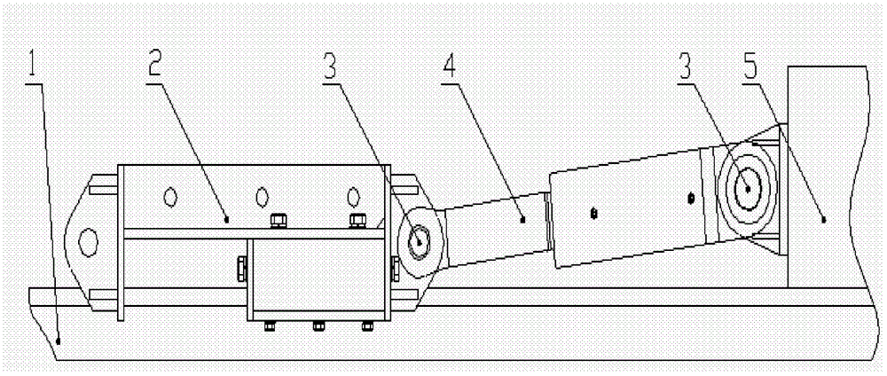
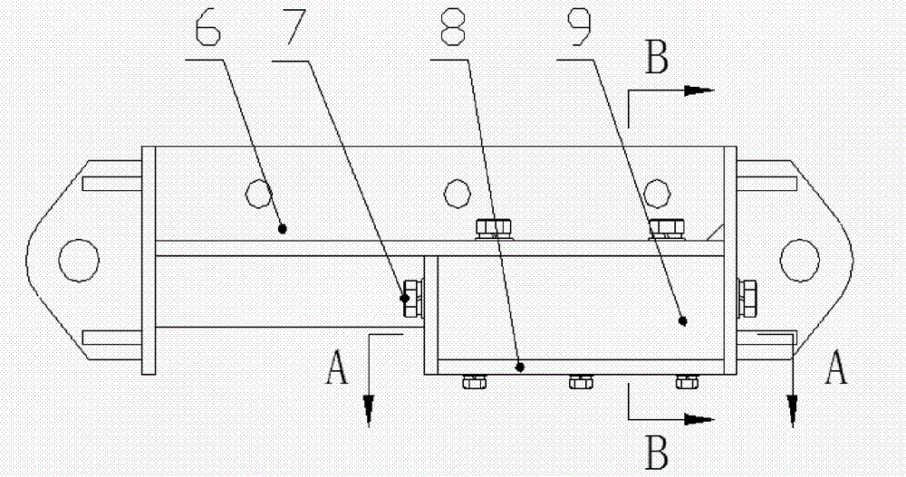
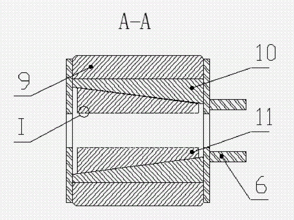
[0030] like Figure 1-5 As shown, the invention of this example is a rail clamping mechanism for hydraulically pushing or dragging heavy objects. The clamping mechanism 2 is connected with one end of the oil cylinder 4, and the other end of the oil cylinder 4 is connected with the weight 5. The clamping mechanism 2 is connected with the weight 5. The weight 5 is placed on the rail 1; the clamping mechanism 2 includes an upper cover plate 6, a lower supporting plate 8, a casing 9, an outer wedge 10 and an inner wedge 11, and the outer wedge 10 and the inner wedge 11 are arranged on the shell Inside the body 9, the slope of the outer wedge 10 is set on the slope of the inner wedge 11, and the opposite side of the slope of the inner wedge 11 is in contact with the side of the rail 1, and the side of the inner wedge 11 is provided with sharp teeth. The left and right sides of the steel rail 1 in the 9 are provided with an outer wedge 10 and an inner wedge 11;

[0031] There are b...


PUM


Abstract

The invention relates to the construction technical field, more specifically a steel rail clamping mechanism for hydraulically jacking or dragging heavy stuff. The clamping mechanism is connected with one end of an oil cylinder, and the other end of the oil cylinder is connected with the heavy stuff; the clamping mechanism and the heavy stuff are arranged on the steel rail; the clamping mechanism comprises an upper cover plate, a lower supporting plate, a housing, an outer wedge block and an inner wedge block, wherein the outer wedge block and the inner wedge block are arranged inside the housing; the inclined plane of the outer wedge block is arranged on the inclined plane of the inner wedge block; one side surface opposite to the inclined plane of the inner wedge block contacts with the side surface of the steel rail; and the upper cover plate is arranged on the top part of the housing, and the lower supporting plate is arranged on the bottom part; the steel rail clamping mechanism adopts a structural form that a self-clamping mechanism clamps left and right sides of the steel rail so as to be easily clamped with and dropped from the steel rail, thus the heavy stuff can be continuously jacked or dragged on the steel rail through the matching with the telescoping of the oil cylinder.

Description

Technical field: [0001] The invention relates to the technical field of construction, and more specifically relates to a rail clamping mechanism for hydraulically pushing or dragging heavy objects. Background technique: [0002] Hydraulic jacking (dragging) equipment is widely used in the translational transportation construction of extra-large and heavy structures and equipment in the fields of roads and bridges, construction, railways, electric power, metallurgy, and petrochemicals. The hydraulic jacking equipment can move along the rails with the object to be pushed, and it mainly consists of two parts, namely the hydraulic jacking cylinder and the clamping device. The construction method of pushing or dragging heavy objects has become a mature construction technology. The clamping device is generally divided into two types. One is the external force clamping type, which is mainly realized by external forces such as the expansion and contraction of the oil cylinder or the...

Claims


Application Information

Patent Timeline
Patent Type & Authority Patents(China)
IPC IPC(8): B66F13/00B66F19/00
Inventor 缪谦江明邹玉英布春磊
Owner CHINA ELECTRIC POWER RES INST
Why Eureka
Try Eureka