Lateral pressure spiral spring and sealing ring with same

A coil spring, side pressure technology, applied in the direction of engine seal, spring, engine components, etc., to achieve the effect of improving dynamic sealing effect and stable preloading force

Inactive Publication Date: 2013-08-21
上海大亚密封技术有限公司
View PDF1 Cites 0 Cited by
  • Summary
  • Abstract
  • Description
  • Claims
  • Application Information

AI Technical Summary

Problems solved by technology

[0005] Although this invention has greatly improved the seal, effectively preventing the ring spring from falling off, but in the working state of the seal, the tensile stress of the ring coil spring can only prevent the diameter of the inner lip of the seal from increasing , but cannot provide a continuous stress compensation to the inner and outer lips of the inner seal ring

Method used


Image

  • Lateral pressure spiral spring and sealing ring with same
  • Lateral pressure spiral spring and sealing ring with same
  • Lateral pressure spiral spring and sealing ring with same

Examples


Embodiment Construction

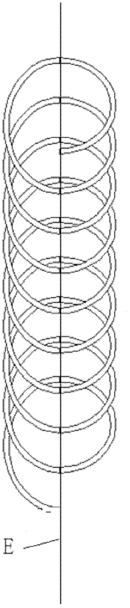
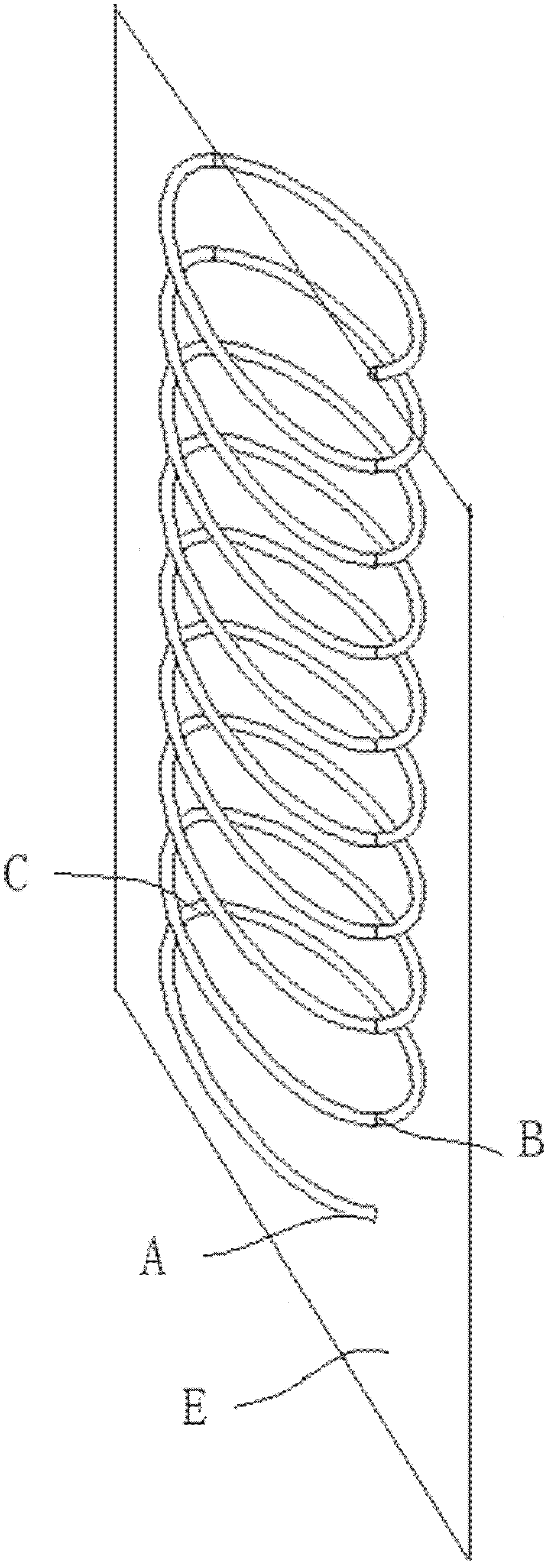
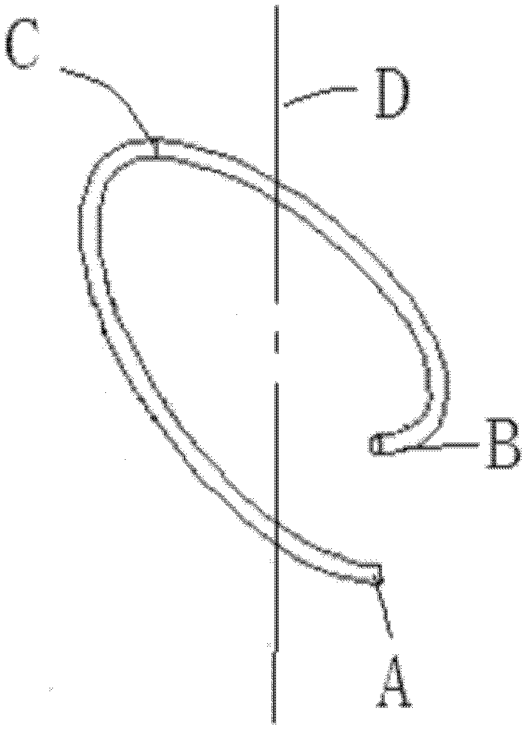
[0030] Such as Figure 1a , 1b , 1c, a side pressure helical spring according to the present invention is formed by winding a central line of linear material and rotating and bending it, and its winding sequence is as follows Figure 1c Shown: Start from the starting point A, rotate around the center line D, gradually rise, after half a circle of inflection point C, change to gradually rotate and descend, and finally reach the end point B, complete a circle; go round and round until the required length. The distance between A and B is the pitch of the spring. Obviously, any point in A, B, and C can be understood as the starting point or inflection point of another circle; thus, a transition surface E of a set of helix angle inflection points is formed between the first half circle and the second half circle, and the transition surface E also Coincides with the centerline D of the spring.

[0031] Such as figure 2 As shown, the unfolded model of a lateral pressure helical s...


PUM


Abstract

The invention provides a lateral pressure spiral spring which is formed by rotating and bending a cylindrical body wound by using linear materials, wherein the axis of the cylindrical body is a central line of the spring, and basic parameters include a material linear diameter, an external diameter of the spring and a spiral angle; and the cylindrical body can be wounded into a cylinder or a ring shape connected end to end. The lateral pressure spiral spring is characterized in that the spiral angle is a variable. The front half circle of the spiral angle is a positive spiral angle, and the rear half circle of the spiral angle is a negative spiral angle; a transitional surface of break points of the spiral angle is formed between the front half circle and the rear half circle, and the absolute value of the positive spiral angle is larger than that of the negative spiral angle; and the spring is in a spiral raising structure as a whole. The spring can be applied to various mechanical application fields and particularly to the sealing field, is wide in stress range and can provide multidirectional stress compensation for elements, the stress compensation direction can be adjusted at any time along with the change of an external acting direction, and the spring can still provide enough stress compensation when pressure stress is not on the same horizontal surface but forms a certain angle with the horizontal surface.

Description

technical field [0001] The invention relates to a helical spring, in particular to a side pressure helical spring capable of realizing multi-directional stress compensation; the invention also relates to a sealing ring equipped with a side pressure helical spring. Background technique [0002] Annular sealing ring is a very widely used mechanical part. It is mostly made of rubber material and is often used as a dynamic seal between shafts and holes. Due to the flexibility of rubber materials, most annular sealing rings have a spring embedded in them. [0003] Since the helical spring in the prior art is formed by winding a cylindrical body with a straight line material, and the helix angle is a constant, the spring can only provide tension or compression stress compensation in the height (ie axis) direction; and Lateral (radial) stress compensation cannot be provided. Therefore, for the annular seals with ordinary coil springs as pre-tightening force, the seals will fail or...

Claims


Application Information

Patent Timeline
Patent Type & Authority Patents(China)
IPC IPC(8): F16F1/00F16J15/32F16J15/3208F16J15/3232F16J15/3284
Inventor 高念平明昌勇
Owner 上海大亚密封技术有限公司
Why Eureka
Try Eureka