High-speed milling tool

A high-speed milling and cutting tool technology, which is applied in the direction of milling cutters, manufacturing tools, milling machine equipment, etc., can solve the problems of unstable tool high-speed rotation structure, complex tool structure, long adjustment time, etc., achieve compact structure, improve cutting efficiency, and structure simple effect

Active Publication Date: 2020-11-06
ZHUZHOU HUARUI PRECISION CUTTINGS TOOLS CO LTD
View PDF14 Cites 0 Cited by
  • Summary
  • Abstract
  • Description
  • Claims
  • Application Information

AI Technical Summary

Problems solved by technology

[0004] The present invention provides a high-speed milling tool, the purpose of which is to solve the existing problems such as complex structure of the tool, long adjustment time, unstable structure of the high-speed rotation of the tool, etc.

Method used


Image

  • High-speed milling tool
  • High-speed milling tool
  • High-speed milling tool

Examples


Embodiment 1

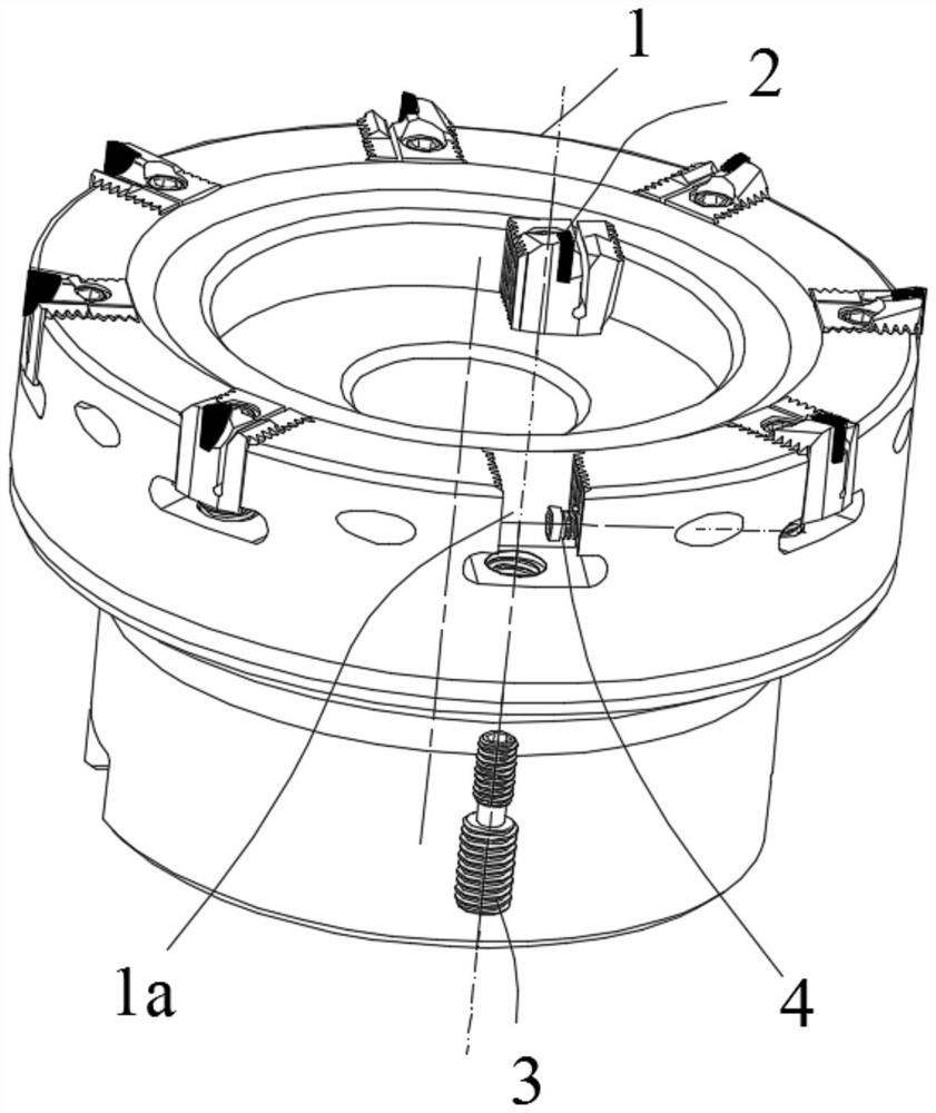
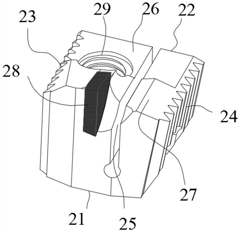
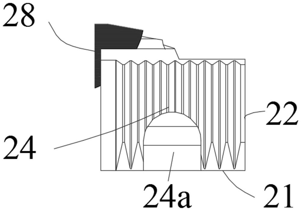
[0045] Such as Figure 1 to Figure 7 As shown, the embodiment of the present invention provides a high-speed milling tool, including: a cutter body 1, the cutter body 1 is a disc-shaped cutter body, a plurality of knife grooves 1a are provided on the cutter body 1, and the cutter body 1 The slot 1a is used to install the cutting unit; the cutting unit includes a tool holder 2, a driving screw 3 and an auxiliary pressing screw 4; The first tangential surface 13 of the knife groove and the second tangential surface 14 of the knife groove are formed. 23 and the second tangential surface 24 of the knife holder; the axial surface 11 of the knife groove, the radial surface 12 of the knife groove, the first tangential surface 13 of the knife groove and the second tangential surface 14 of the knife groove are respectively connected with the knife holder The axial surface 21, the radial surface 22 of the tool holder, the first tangential surface 23 of the tool holder and the second ta...

Embodiment 2

[0064] Such as Figure 14 and 15 As shown, embodiment 2 of the present invention provides a kind of high-speed milling cutter, comprises: cutter body 1, and described cutter body 1 is disc-shaped cutter body, and described cutter body 1 is uniformly provided with a plurality of sipes 1a, so The sipe 1a is used to install the cutting unit; the cutting unit includes a tool holder 2, a driving screw 3 and an auxiliary compression screw 4; each of the sipe 1a is composed of a sipe axial surface 11, a sipe radial surface 12. The first tangential surface 13 of the knife groove and the second tangential surface 14 of the knife groove are formed. To the surface 23 and the second tangential surface 24 of the knife holder; the axial surface 11 of the sipe, the radial surface 12 of the sipe, the first tangential surface 13 of the sipe and the second tangential surface 14 of the sipe are respectively connected with the The tool holder axial surface 21, the tool holder radial surface 22,...

Embodiment 3

[0067] Such as Figure 16 and Figure 17As shown, embodiment 3 of the present invention provides a kind of high-speed milling cutter, comprises: cutter body 1, and described cutter body 1 is disc-shaped cutter body, and described cutter body 1 is uniformly provided with a plurality of sipes 1a, so The sipe 1a is used to install the cutting unit; the cutting unit includes a tool holder 2, a driving screw 3 and an auxiliary compression screw 4; each of the sipe 1a is composed of a sipe axial surface 11, a sipe radial surface 12. The first tangential surface 13 of the knife groove and the second tangential surface 14 of the knife groove are formed. To the surface 23 and the second tangential surface 24 of the knife holder; the axial surface 11 of the sipe, the radial surface 12 of the sipe, the first tangential surface 13 of the sipe and the second tangential surface 14 of the sipe are respectively connected with the The tool holder axial surface 21, the tool holder radial surf...


PUM


Abstract

The invention provides a high-speed milling tool which comprises a tool body, tool grooves, a tool clamp, a driving screw and auxiliary pressing screws. Each tool groove is provided with a tool grooveaxial surface, a tool groove radial surface, a tool groove first tangential surface and a tool groove second tangential surface. The tool clamp is provided with a tool clamp axial surface, a tool clamp radial surface, a tool clamp first tangential surface and a tool clamp second tangential surface. The tool clamp first tangential surface and the tool clamp second tangential surface are oppositelydisposed and tilted to each other at an acute angle a. The tool clamp is divided by at least one seam into a fixed part and an elastic part. The fixed part is provided with a cutting part. A drivingscrew hole is formed in the fixed part. The tool clamp moves in the tool grooves when the driving screw is matched with the driving screw hole. The high-speed milling tool is reasonable in structuraldesign, convenient to adjust and stable in structure and cannot fly out under force, meanwhile the elastic part of the tool clamp can provide a similar 'damping' effect, microvibration of the tool clamp during cutting is reduced, and the service life of the tool is prolonged.

Description

technical field [0001] The invention relates to the technical field of milling tools, in particular to a high-speed milling tool. Background technique [0002] With the advancement of cutting technology, milling cutters equipped with welded PCD toolholders are widely used in high-speed milling of aluminum alloys. In order to ensure the life of the tool and the cutting effect, the tool often adopts the following structure, namely: disc-shaped cutter body and set on A cutting unit that can be adjusted axially in the peripheral groove of the cutter body; each cutting unit includes the following structures: cutting tool holder, pressing unit and adjustment unit; in order to ensure the cutting effect of the tool when it is used, such tools are It is necessary to adjust the axial height of each tool holder to ensure the accuracy. The adjustment sequence is: 1. The adjustment unit roughly adjusts the cutting tool holder to the initial predetermined height; 2. The pressing unit pre-...

Claims


Application Information

Patent Timeline
Patent Type & Authority Applications(China)
IPC IPC(8): B23C5/18B23C5/00
CPCB23C5/18B23C5/00
Inventor 仵永博肖旭凯高江雄陈胜男
Owner ZHUZHOU HUARUI PRECISION CUTTINGS TOOLS CO LTD
Why Eureka
Try Eureka