
A gyro motor bearing unit

A gyro motor and bearing technology, applied in bearing components, ball bearings, electrical components, etc., can solve the problems of low installation qualification rate, low rotation accuracy, low reliability, etc., to improve the installation qualification rate, prolong bearing life, installation Simple and fast effects

Active Publication Date: 2016-10-19
LUOYANG BEARING RES INST CO LTD
View PDF4 Cites 0 Cited by
  • Summary
  • Abstract
  • Description
  • Claims
  • Application Information

AI Technical Summary

Problems solved by technology

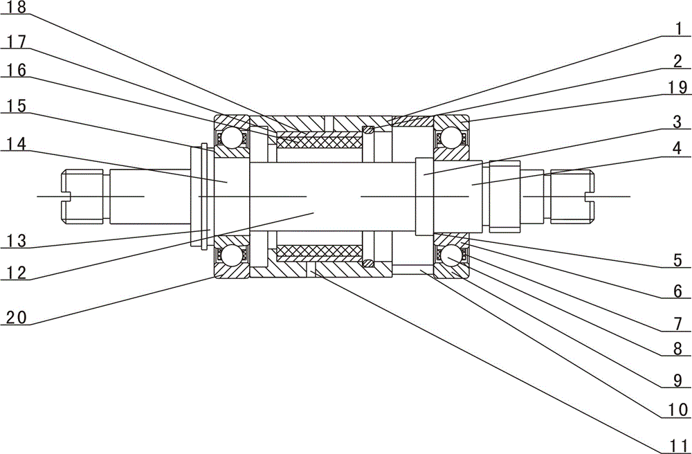
[0003] In order to achieve the purpose of the invention, the present invention discloses a gyro motor bearing unit. The gyro motor bearing unit sets the step shaft 12 as a multi-stage step, and two sets of angular contact ball bearings with different inner diameters are installed back to back. On the stepped shaft 12, the inner ring 6 of the angular contact ball bearing and the stepped shaft 12 adopt an interference fit, so that the inner ring 6 and the stepped shaft 12 form an integral combined structure, and the elastic bushing 1 and the U-shaped collar 10 are used to pair the bearing A small axial constant pressure preload is applied, and the supplementary lubrication of the bearing is realized through the oil storage ring 16; the present invention overcomes the low rotation accuracy, short life, low reliability and low qualified rate of the traditional gyro motor bearing unit, etc. Shortcomings, effectively improve the performance of the gyro motor bearing unit

Method used


Image

  • A gyro motor bearing unit

Examples


Embodiment Construction

[0024] The present invention will be further described below in conjunction with specific examples, so that those skilled in the art can further understand the present invention, but the following examples are not intended to limit the protection scope of the present invention.

[0025] combined with figure 1 The gyro motor bearing unit includes a stepped shaft 12, a bearing A19, a bearing B20, an oil storage ring 16, an oil storage ring bush 18, an elastic bush 1 and a U-shaped collar 10, on both sides of the middle of the stepped shaft 12 A bearing A19 and a bearing B20 are respectively provided, and the bearing A19 and the bearing B20 are angular contact ball bearings, and the angular contact ball bearings are installed in a back-to-back manner; the bearing A19 and the bearing B20 respectively include inner rings 6, The outer ring 9, the rolling elements 8 and the cage 7 are provided with the outer ring 9 on the outside of the inner ring 6, and the rolling elements 8 are ar...


PUM


Abstract

The invention discloses a gyro motor bearing unit and relates to the field of the design technologies of the bearings. The gyro motor bearing unit comprises a step shaft (12), a bearing A (19), a bearing B (20), an oil storage ring (16), an oil storage ring lining (18), an elastic lining (1) and a U-shaped clamping ring (10), wherein the bearing A and the bearing B are arranged on two sides of the middle part of the step shaft (12); the elastic lining and the U-shaped clamping ring are arranged between the bearings A and B; the U-shaped clamping ring is arranged between the elastic lining and the bearing A; the oil storage ring is arranged in a groove body which is formed in the middle part of the inner surface of the elastic lining; an oil storage ring lining is arranged between the oil storage ring and the groove body of the elastic lining. The gyro motor bearing unit overcomes such defects of the conventional gyro motor bearing unit as low rotation precision, short service life, low reliability and poor installation qualified rate; and the performance of the gyro motor bearing unit can be effectively improved.

Description

technical field [0001] The invention relates to the technical field of bearings, in particular to a gyroscope motor bearing unit. Background technique [0002] As is known, the current domestic flexible gyro motor bearing unit generally adopts a structure in which a conventional gyro motor drive shaft is combined with two sets of separate angular contact ball bearings of the same size through inner and outer rigid bushes to apply axial positioning preload. ;In order to facilitate assembly, the inner ring of the bearing and the shaft are matched with a small clearance. Due to the existence of a small clearance, the rotation accuracy of the bearing is reduced, and the axial preload of the bearing needs to be accurate by repairing the height of the inner and outer rigid bushings. control, thereby reducing the accuracy, performance and installed pass rate of the gyro motor; the general gyro motor has a small size, and the bearing unit is not allowed to be attached to other suppl...

Claims


Application Information

Patent Timeline
Patent Type & Authority Patents(China)
IPC IPC(8): F16C19/16H02K7/08F16C33/58F16C33/66
Inventor 程俊景葛世东孙北奇于晓凯姜维屈驰飞
Owner LUOYANG BEARING RES INST CO LTD
Learn More