Super-large numerical control vertical mill machine

A vertical mill, extra-large technology, applied in the direction of grinding frame, grinding machine parts, grinding machines, etc., can solve problems such as floating, bearing pre-tightening is not in place, so as to eliminate floating amount and prolong service life , the effect of high processing precision

Active Publication Date: 2018-10-16
ZHEJIANG 81 PRECISION MACHINERY CO LTD
View PDF15 Cites 0 Cited by
  • Summary
  • Abstract
  • Description
  • Claims
  • Application Information

AI Technical Summary

Problems solved by technology

[0005] In view of the above problems, the present invention provides a super-large CNC vertical mill. By setting a hydraulic mechanism on the processing platform of the traditional CNC vertical mill, the pressure of the hydraulic mechanism is used to drive the main shaft to sink when it is working, and then to drive The working platform is lowered to pre-tighten the various bearings installed on the working platform and the main shaft. When it is not working, the hydraulic mechanism discharges hydraulic oil to release the bearings, which solves the problem that the bearing pre-tightening is not in place during the working process and the working platform floats To solve the technical problems of the working platform, eliminate the floating amount of the working platform, improve the bearing capacity, shock absorption, stability and service life of the working platform

Method used


Image

  • Super-large numerical control vertical mill machine
  • Super-large numerical control vertical mill machine
  • Super-large numerical control vertical mill machine

Examples


Embodiment 1

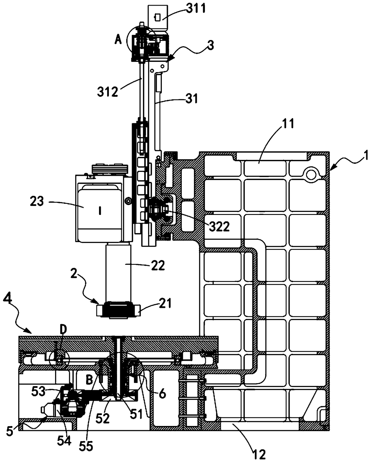
[0049] Such as figure 1 , figure 2 , image 3 , Figure 4 , Figure 6 Shown, a kind of extra-large numerical control vertical mill, comprises frame 1, and this frame 1 comprises the vertical arm 11 of vertical setting and the body 12 of horizontal setting, also comprises:

[0050] Grinding head mechanism 2, said grinding head mechanism 2 is arranged on said vertical arm 11, and it is movably connected with the frame 1 through an adjustment mechanism 3, and the adjustment mechanism 3 includes a longitudinal adjustment assembly 31 and a lateral adjustment assembly 32 , the longitudinal adjustment assembly 31 is vertically arranged on the vertical arm 11, and the horizontal adjustment assembly 32 is horizontally arranged on the vertical arm 11;

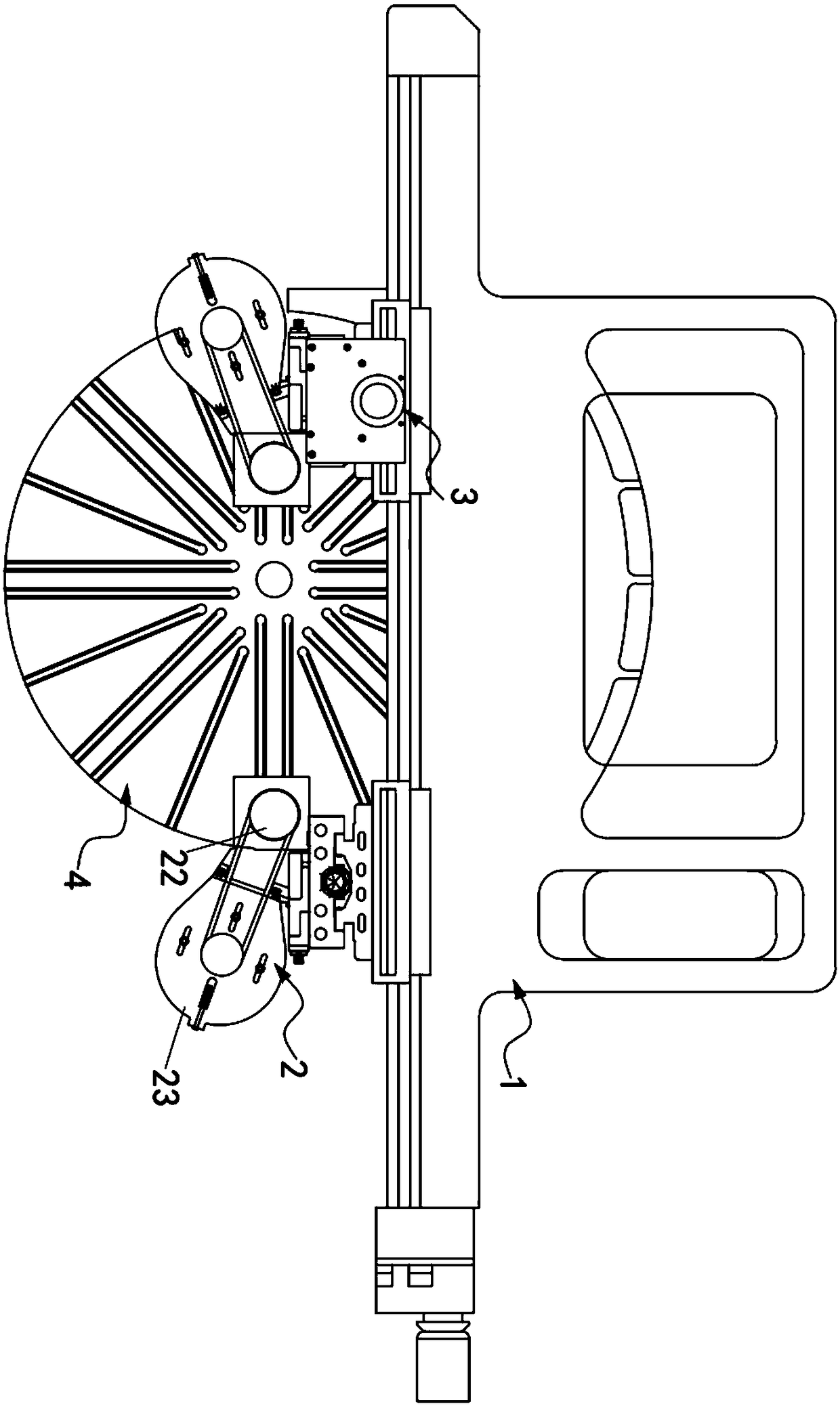
[0051] Processing platform 4, described processing platform 4 is circular setting, and it is erected on described body 12, and first bearing 40 is arranged between its circumference and described body 12;

[0052] A driving mechani...

Embodiment approach

[0066] Such as figure 1 As shown, as a preferred embodiment, the drive mechanism 5 also includes:

[0067] A driven pulley 52, the driven pulley 52 is sleeved on the end of the main shaft 51;

[0068] The driving pulley 53 , the driving pulley 53 is arranged on one side of the driven pulley 52 , is coaxially connected with the drive motor 54 , and is connected with the driven pulley 52 through a belt 55 .

[0069] It should be noted that the drive motor 54 is connected to the main shaft 51 through a belt drive, but this embodiment is not limited to the belt drive connection.

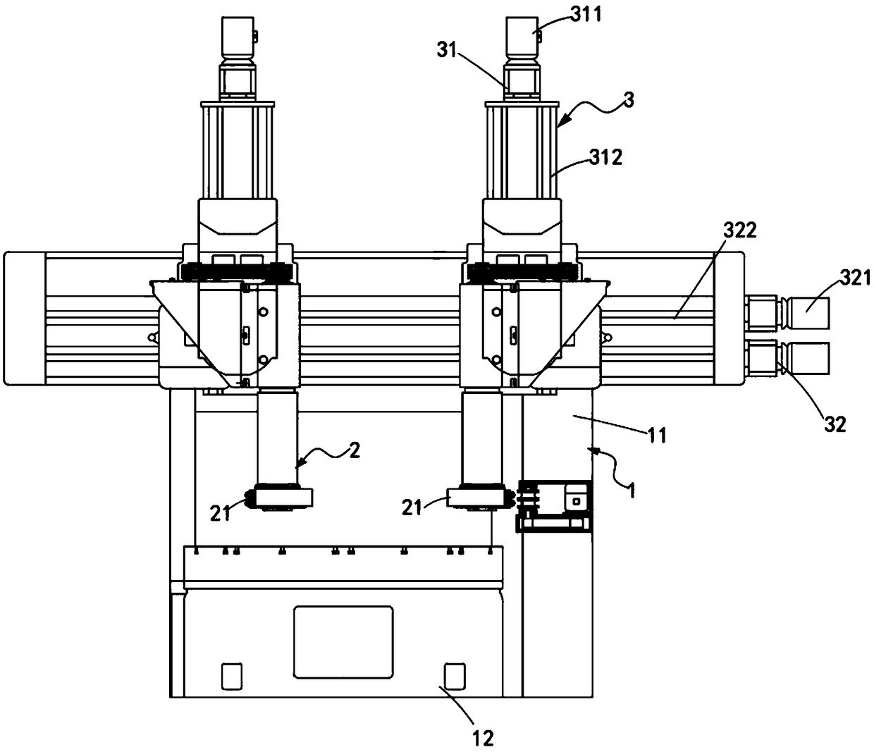
[0070] Such as figure 1 and image 3 As shown, as a preferred embodiment, the grinding head mechanism 2 is driven by the adjustment mechanism 3 to move horizontally and vertically, and the grinding head mechanism 2 includes:

[0071] There are two grinding heads 21, the grinding heads 21 are arranged symmetrically on the vertical arm 11, and the grinding heads 21 are arranged horizontally;

[0072] ...

Embodiment 2

[0082] Figure 7 It is a structural schematic diagram of Embodiment 2 of an extra-large numerically controlled vertical mill of the present invention; as Figure 7 As shown, the parts that are the same as or corresponding to those in Embodiment 1 use the reference numerals corresponding to Embodiment 1. For the sake of simplicity, only the differences from Embodiment 1 will be described below. This embodiment two and figure 1 The difference of the shown embodiment one is:

[0083] Such as Figure 7 As shown, a super large CNC vertical mill, the top of the screw 3121 is provided with a first adjustment bearing 33 and a second adjustment bearing 34, the upper and lower sides of the first adjustment bearing 33 and the second adjustment bearing 34 Spacer sleeves 35 and pre-tightening sleeves 36 are respectively provided at the ends, and the pre-tightening sleeves 36 are set around the screw 3121 in a complete circle.

[0084] It should be noted that when the traditional bearin...


PUM


Abstract

The invention provides a super-large numerical control vertical mill machine. The super-large numerical control vertical mill machine comprises a rack, a grinding head mechanism, an adjusting mechanism, a machining platform, a driving mechanism and a hydraulic mechanism. According to the super-large numerical control vertical mill machine, the hydraulic mechanism is arranged on a machining platform of a traditional numerical control vertical mill machine. During operation, the super-large numerical control vertical mill machine drives a spindle to drop through pressure of the hydraulic mechanism and then drives an operating platform to drop to pre-tighten bearings mounted on the operating platform and the spindle. However, during non-operation, the hydraulic mechanism discharges hydraulicoil to release the bearings. The technical problems that the bearings are pre-tightened in place and the operating platform floats up in the operating process are solved. The floating amount of the operating platform is eliminated. The bearing capacity, shock absorption and stability of the operating platform are improved, and the service life of the bearings is prolonged.

Description

technical field [0001] The invention relates to the technical field of mechanical processing, in particular to an extra-large numerically controlled vertical mill. Background technique [0002] The rotary table device of the traditional vertical grinding machine is generally composed of workpiece spindle, sleeve, workbench lower seat, workbench and pulley and other parts. The upper end of the workpiece spindle adopts double-row cylindrical roller bearings, the lower end of the spindle is equipped with tapered roller bearings and springs for bearing preload, the periphery of the workpiece spindle is equipped with flat thrust ball roller bearings, and the sleeve and workpiece spindle assembly are fixed in the working position. Put it on the seat under the table, and then fix it on the bed together. The lower end of the workpiece spindle is equipped with a pulley. Because the radial and axial support of this set of devices all adopt rolling bearings, the bearings are easy to ...

Claims


Application Information

Patent Timeline
Patent Type & Authority Applications(China)
IPC IPC(8): B24B27/00B24B27/02B24B41/02B24B41/04B24B47/06B24B55/00B24B41/00
CPCB24B27/0015B24B27/0046B24B27/02B24B41/007B24B41/02B24B41/04B24B47/06B24B55/00Y02P70/10
Inventor 陈仁波胡龙流陈柱陈美华毛丽丽宗煜景余国朋
Owner ZHEJIANG 81 PRECISION MACHINERY CO LTD
Why Eureka
Try Eureka