Eureka AIR delivers breakthrough ideas for toughest innovation challenges, trusted by R&D personnel around the world.

Atomatic transmission performance and fault detection apparatus and method thereof

An automatic transmission and fault detection technology, applied in the direction of machine gear/transmission mechanism testing, etc., can solve the problems of uneven maintenance personnel, multiple repairs, and complicated and difficult reasons for failures.

Inactive Publication Date: 2012-06-13
TIANJIN UNITE AUTOMOBILE ELECTRONICS CONTROL TECH SERVICE
View PDF9 Cites 22 Cited by
  • Summary
  • Abstract
  • Description
  • Claims
  • Application Information

AI Technical Summary

Problems solved by technology

In production and manufacturing, the automatic transmission must go through various performance tests from production to market; when the automatic transmission fails, in the existing automobile maintenance industry, the automatic transmission is generally repaired by the maintenance personnel on their own. Assess the fault based on experience to see where the fault occurs, but because the level of maintenance personnel is also uneven, and the structure of the automatic transmission is relatively complicated, integrating machine, electricity, and hydraulics, the cause of the fault is complicated and difficult to distinguish, so this In this case, it is easy to cause misjudgment or even misjudgment, resulting in the situation that the real fault cannot be eliminated and needs to be repaired many times; The cost of the detection device and method is too high, so a device and method capable of detecting the performance and faults of different types of automatic transmissions are currently required on the market

Method used


Image

  • Atomatic transmission performance and fault detection apparatus and method thereof
  • Atomatic transmission performance and fault detection apparatus and method thereof
  • Atomatic transmission performance and fault detection apparatus and method thereof

Examples


Embodiment Construction

[0035] The automatic transmission performance and fault detection device and method of the present invention will be described in detail below with reference to the accompanying drawings.

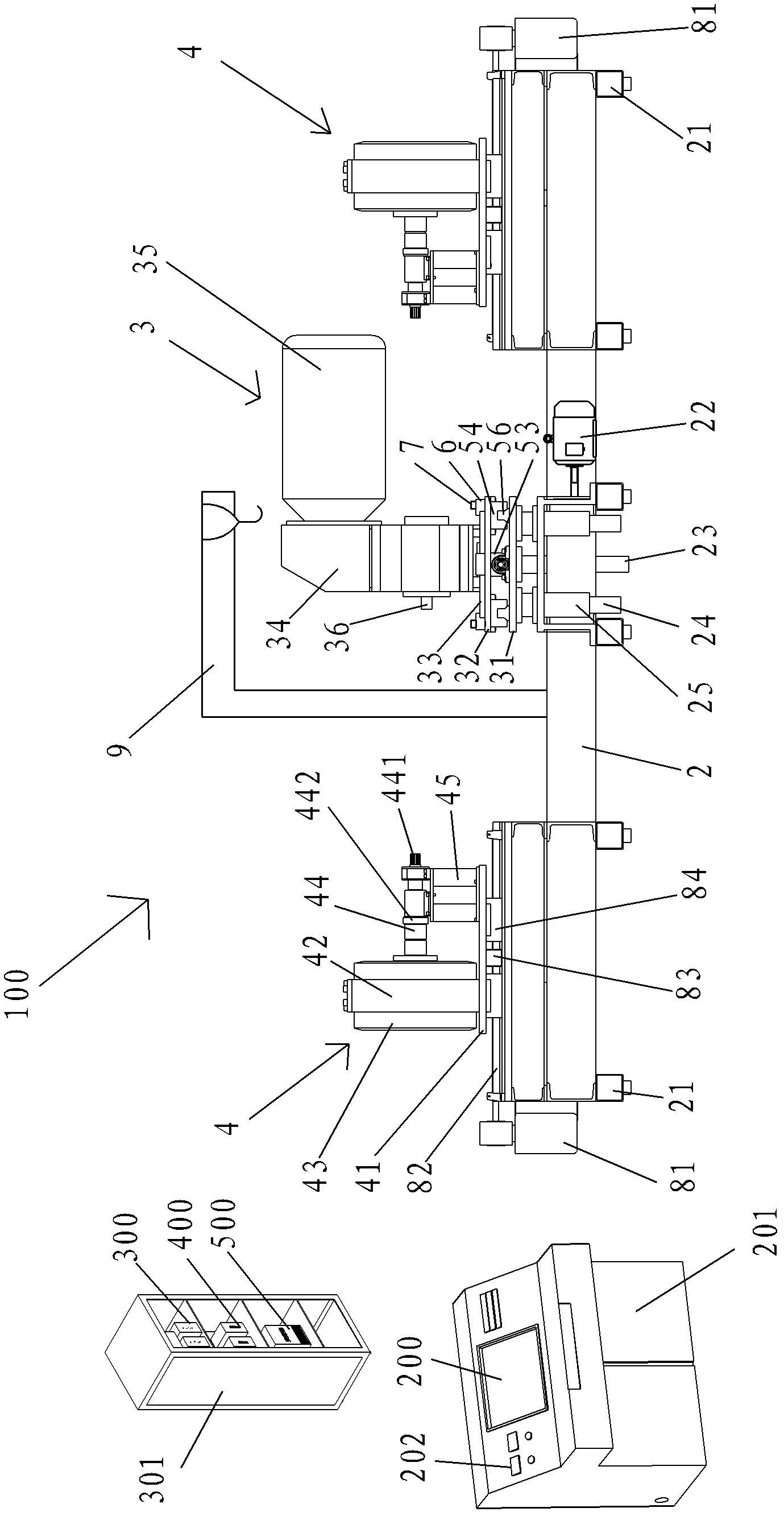
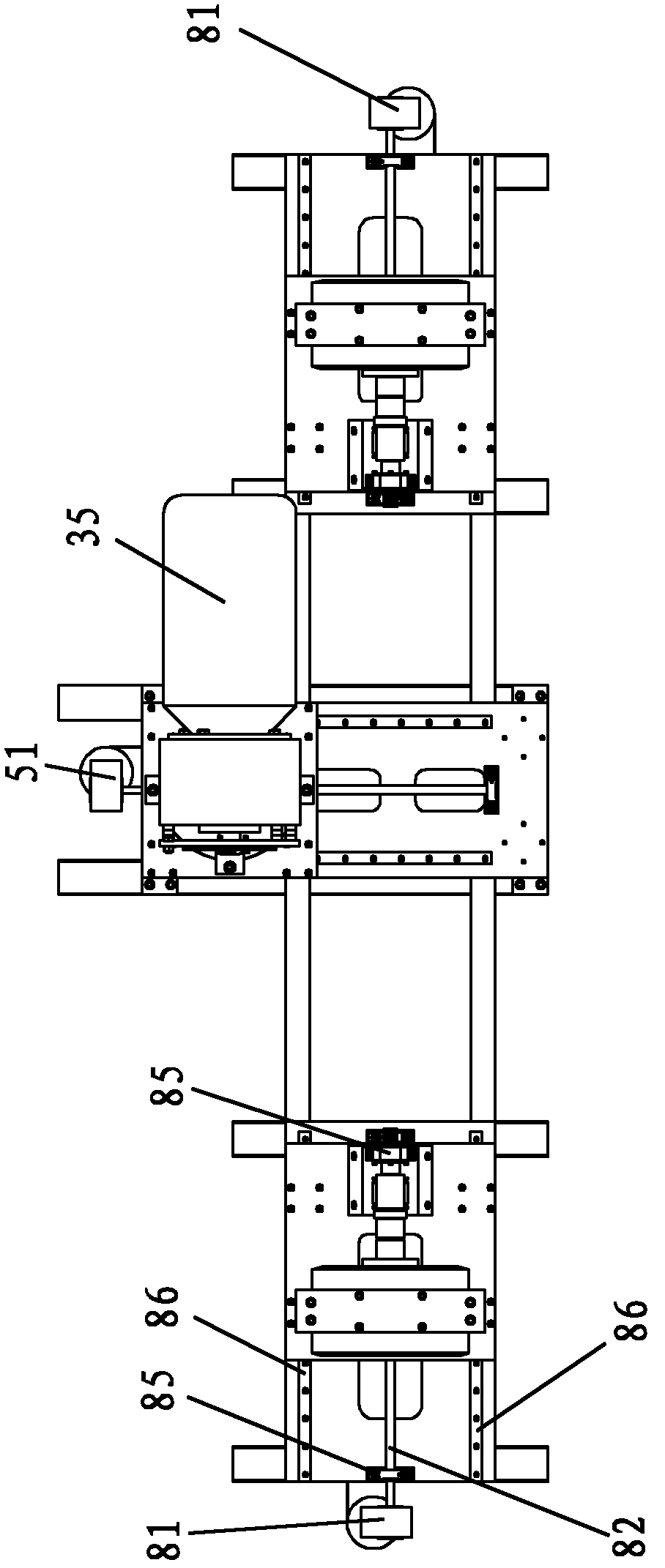
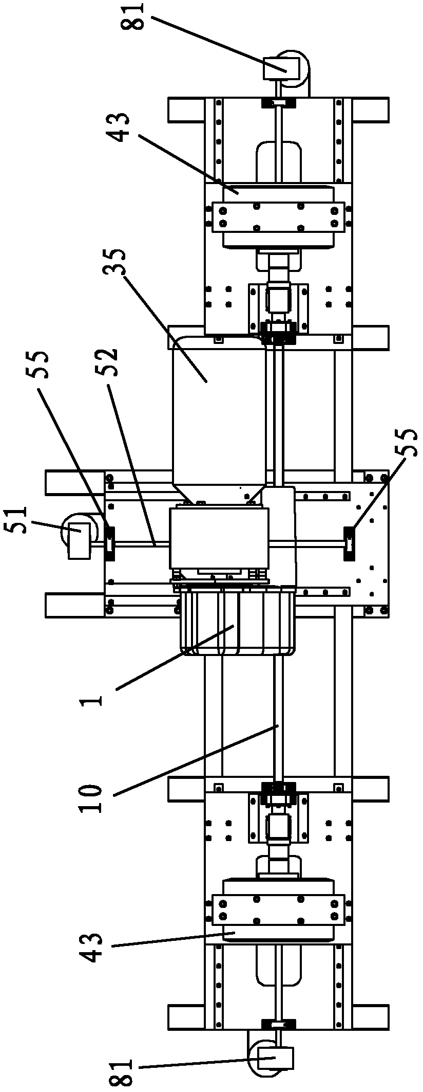
[0036] Such as figure 1 As shown, the automatic transmission performance and fault detection device of the present invention includes a test bench 100 for positioning the self-transmission 1 , a control terminal, multiple relays 300 , a frequency converter control module 400 , and a loading control module 500 .

[0037]In this embodiment, the control terminal is a computer 200, and control software is pre-installed in the computer 200, and the control software also includes various theoretical values ​​of the automatic transmission in different states, and the computer 200 is set In a cabinet 201; the plurality of relays 300, the frequency converter control module 400, and the loading control module 500 are all placed in an electrical cabinet 301, and a plurality of display instruments (not...


PUM


Abstract

The invention discloses a testboard used for detecting automatic transmission performance and a fault. The testboard comprises a pedestal, a variable-frequency and variable-speed motor and a load loader, wherein the variable-frequency and variable-speed motor and the load loader are arranged on the pedestal. An input terminal of an automatic transmission is connected with the variable-frequency and variable-speed motor and an output terminal is connected with the load loader. A computer inputs an instruction to a frequency converter control module so as to make the variable-frequency and variable-speed motor simulate an engine and provide power for the automatic transmission. The computer inputs the instruction to a loading control module so as control the load applied to an automatic transmission output shaft by the load loader and simulate a pavement state of a wheel. Actual data collected by a sensor is returned to the computer and compared with theoretical data. If the two data are consistent, the automatic transmission performance is qualified and there is no fault. If the two data are inconsistent, the automatic transmission performance is not qualified and there is the fault. A frequency conversion speed regulator can move and rotate back and forth, up and down relatively to the pedestal and a loading device can move left and right relatively to the pedestal. Therefore, the apparatus and the method can be suitable for different models of the automatic transmissions.

Description

technical field [0001] The invention relates to a device and a method for detecting the performance and failure of auto parts, in particular to a device and method for detecting the performance and failure of an automatic transmission. Background technique [0002] With the development of our country's social economy, the number of cars is also increasing, and automatic transmissions are widely used because of their simple operation. In production and manufacturing, the automatic transmission must go through various performance tests from production to market; when the automatic transmission fails, in the existing automobile maintenance industry, the automatic transmission is generally repaired by the maintenance personnel on their own. Assess the fault based on experience to see where the fault occurs, but because the level of maintenance personnel is also uneven, and the structure of the automatic transmission is relatively complicated, integrating machine, electricity, an...

Claims


Application Information

Patent Timeline
Patent Type & Authority Applications(China)
IPC IPC(8): G01M13/02
Inventor 王征
Owner TIANJIN UNITE AUTOMOBILE ELECTRONICS CONTROL TECH SERVICE
Why Eureka
Eureka Blog
Learn More