Sealed forcible trigger gap

A technology of triggering gap and sealing unit, which is applied to emergency protection circuit devices, electrical components, circuit devices and other directions for limiting overcurrent/overvoltage, which can solve the limitation of trigger gap adjustment range, inaccurate concentricity, and inability to adjust distance. and other problems, to achieve the effect of large gap adjustment range, long service life and good consistency

Inactive Publication Date: 2012-06-13
RONGXIN POWER ELECTRONICS
View PDF3 Cites 3 Cited by
  • Summary
  • Abstract
  • Description
  • Claims
  • Application Information

AI Technical Summary

Problems solved by technology

However, the distance between the two electrodes of the trigger gap in the prior art cannot be adjusted, and the concentricity is inaccurate; the adjustment range of the trigger gap is limited by the structure

Method used


Image

  • Sealed forcible trigger gap
  • Sealed forcible trigger gap
  • Sealed forcible trigger gap

Examples


Embodiment Construction

[0018] The technical content of the present invention will be further described in detail below in conjunction with the accompanying drawings.

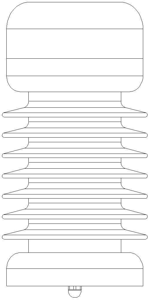
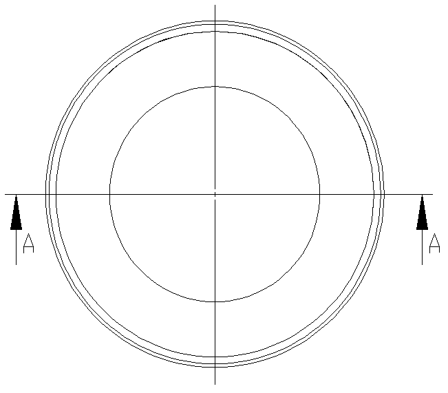
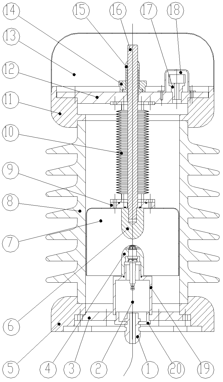
[0019] See Figure 1-Figure 4 , Seal the forced trigger gap, the trigger gap adopts a closed structure in a cylinder, including a sealing unit, an arc strike unit, a discharge unit, a gas injection unit, and an electrode adjustment unit.

[0020] The sealing unit is composed of an upper cover 12, a lower cover 3, a ceramic umbrella skirt 8, a rain cover 13, a lower fixing seat 5 and an upper fixing seat 11. The rain cover 13 is located outside the upper end cover 12 and the guide rod 16. The upper end cover 12 and the lower end cover 3 are fixedly connected with the ceramic umbrella skirt 8 through the upper end holder 11 and the lower end holder 5 respectively. Vacuum and fill with inert gas.

[0021] The arc striking unit is composed of a three-head spark plug 2, a cable jacket 1, and a jacket lock cover 20. The three-head spark p...


PUM


Abstract

The invention relates to a sealed forcible trigger gap comprising an arc ignition unit, a sealing unit, a discharging unit, and a gas injection unit. The trigger gap has a cylindrical enclosed structure. Besides, the trigger gap is characterized in that: an electrode adjusting unit is also arranged and is composed of a vacuum bellows, an adjusting nut, a locking nut, and a guide rod having an adjusting scale; the guide rod is connected with an upper electrode of the discharging unit; the vacuum bellows is at an external portion of the guide rod; the top of the guide rod penetrates an upper end enclosing cover and the guide rod is fixed with the upper end enclosing cover by the adjusting nut and the locking nut; on the basis of adjustment of the adjusting nut, the upper electrode makes up-and-down lifting movements with the guide rod under the guiding effects of an arc shield and an inner wall of a ceramic umbrella skirt; and the upper electrode is locked by the locking nut; therefore, it can be ensured that a gap between the upper electrode and a lower electrode can be accurately adjusted. According to the sealed forcible trigger gap provided by the invention, good consistency of triggered voltages can be ensured; spacing between two electrodes can be adjusted; and three-point arc ignition is employed, so that reliability of electrode triggering for discharging can be improved.

Description

technical field [0001] The invention relates to a sealed forced trigger gap, which is used in electric power, metallurgy and all other electrical fields using protection circuits, and can be used for self-triggering protection circuits of 220kV and above voltage levels and protection circuits requiring forced triggering. Background technique [0002] At present, the trigger gap is widely used in the electrical field. The trigger gap mainly uses electrode discharge to suppress the overvoltage of the equipment and improve the stability of the system. However, the distance between the two electrodes in the trigger gap in the prior art cannot be adjusted, and the concentricity is inaccurate; the adjustment range of the trigger gap is limited by the structure. Contents of the invention [0003] The purpose of the present invention is to provide a sealed forced trigger gap, which can ensure better consistency of the trigger voltage, the distance between the two electrodes can be...

Claims


Application Information

Patent Timeline
Patent Type & Authority Applications(China)
IPC IPC(8): H02H9/06
Inventor 侯小平靳久大
Owner RONGXIN POWER ELECTRONICS
Why Eureka
Try Eureka