Direct power control method of voltage source PWM (pulse width modulation) rectifier system

A power control and rectifier technology, applied in the field of electrical transmission, can solve the problems of poor steady-state performance of PWM rectifier system and high harmonic content of grid-side current, and achieve good dynamic and static characteristics, optimized performance, and optimized control.

Inactive Publication Date: 2012-06-13
SOUTHEAST UNIV
View PDF2 Cites 21 Cited by
  • Summary
  • Abstract
  • Description
  • Claims
  • Application Information

AI Technical Summary

Benefits of technology

This patented technology improves upon existing methods by adding an indicator called Active Power (AP) or Reactionary Power Control (R PC). By doing it correctly during normal operation, these techniques help regulate both active and reactive powers simultaneously while minimizing interference between them. Additionally, they allow for tracking changes over time within specific ranges based on their respective levels of activity. Overall, this innovation optimizes energy management systems' ability to efficiently manage electrical loads effectively.

Problems solved by technology

This patented technical problem addressed in this patent relates to controller systems for electronic converters such as pulsed inductive load circuits (PLC). These are designed to convert electrical signals from analog sources like voltages to different forms suitable for transmission over communication networks. However, these conventional techniques suffer drawbacks including lack of flexibility in adapting input/output characteristics during operation due to changes caused by external factors such as temperature fluctuations. To address this issue, new solutions involving advanced mathematical models called Volterra Neural Networks (VNN), artificial neural network architectures, and more recently developed hybrid approaches were discussed.

Method used


Image

  • Direct power control method of voltage source PWM (pulse width modulation) rectifier system
  • Direct power control method of voltage source PWM (pulse width modulation) rectifier system
  • Direct power control method of voltage source PWM (pulse width modulation) rectifier system

Examples


Embodiment

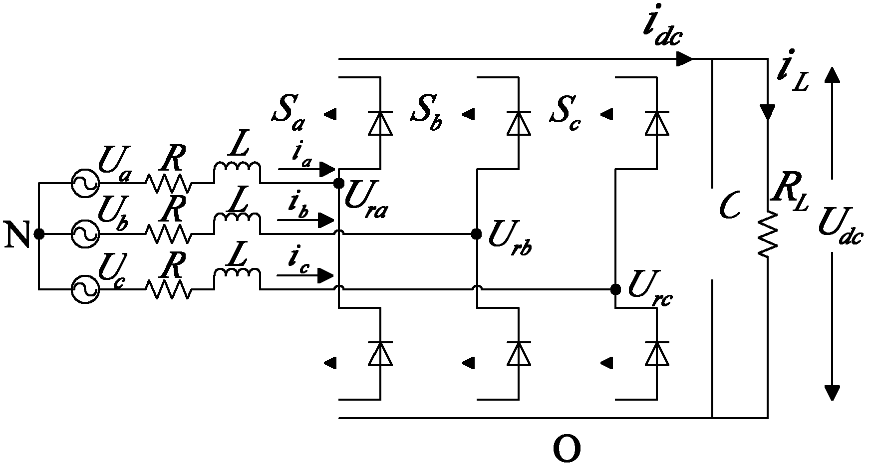
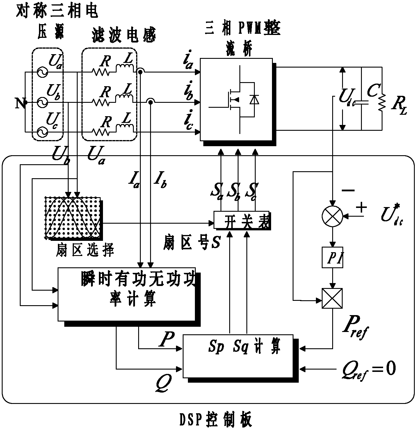
[0033] Example: Press figure 2 The structure shown, the simulation model is built in MATLAB / simulink environment, the parameters are as follows: the initial value of load resistance is R L =22Ω, connected by 5 110Ω resistors in parallel, cut off two resistors when the load changes suddenly, R L ’=110 / 3Ω; filter inductance L=7mH; filter capacitor C=3000μF; current inner loop PI regulator proportional constant K p =0.8, integral constant K i =0.2; H p =H q = 4W, S p =S q = 4. The simulation result is shown in Figure 5. The grid-side A-phase current waveform is sinusoidal. The actual system uses a three-phase three-wire isolation transformer, which corresponds to the actual measurement results. Figure 5(a) shows the BC phase line voltage and the A phase current. The A phase current leads the BC phase line voltage. At 90°, it can be seen from Figure 5(b) that the active and reactive power input by the rectifier is decoupled, and the reactive power is basically zero, achieving unity...


PUM


Abstract

The invention provides a direct power control method of a voltage source PWM (pulse width modulation) rectifier system. Based on an inner-loop power and outer-loop voltage control method adopted in a DPC (data processing control) method, set values of active power and reactive power are compared with actual values, and a voltage vector is selected by querying a switch list to control the on-off state of the PWM rectifier. According to the control method provided by the invention, a state variable marking the active power and the reactive power is added, the location of a space vector is redefined and a segmented switch list is constructed, thus enhancing the decoupling control on the active power and the reactive power and the response capability, and improving the power factor of the rectifier. The calculation and experiment results show that the grid side input current is sine and the instantaneous power dynamic and static control characteristics of the system are better.

Description


Claims


Application Information

Patent Timeline
Owner SOUTHEAST UNIV
Why Eureka
Try Eureka