Open type intelligent milling system and milling method based on same

A milling and open technology, applied in the field of machining, can solve the problems that affect the efficiency of CNC machining, the key parameters cannot be adjusted in real time, and the machining parameters cannot maintain the machining target, etc., and achieve the effect of increasing intelligent features.

Active Publication Date: 2013-06-05
HARBIN INST OF TECH
View PDF4 Cites 0 Cited by
  • Summary
  • Abstract
  • Description
  • Claims
  • Application Information

AI Technical Summary

Problems solved by technology

[0003] The purpose of the present invention is to solve the existing milling processing system optimized by offline algorithm. The processing parameters of its offline optimization cannot maintain the optimal processing target, and the key parameters cannot be adjusted in real time during the processing, thus affecting the numerical control processing. In order to solve the problem of efficiency, an open intelligent milling processing system and a milling processing method based on the system are provided

Method used


Image

  • Open type intelligent milling system and milling method based on same
  • Open type intelligent milling system and milling method based on same
  • Open type intelligent milling system and milling method based on same

Examples


specific Embodiment approach 1

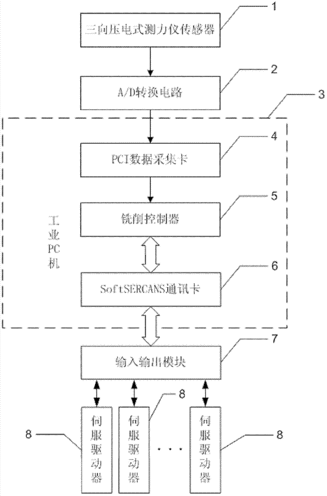
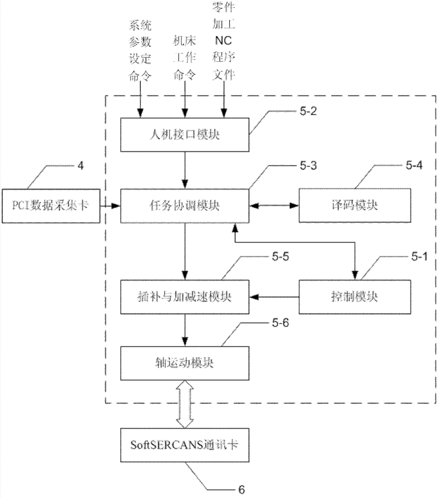
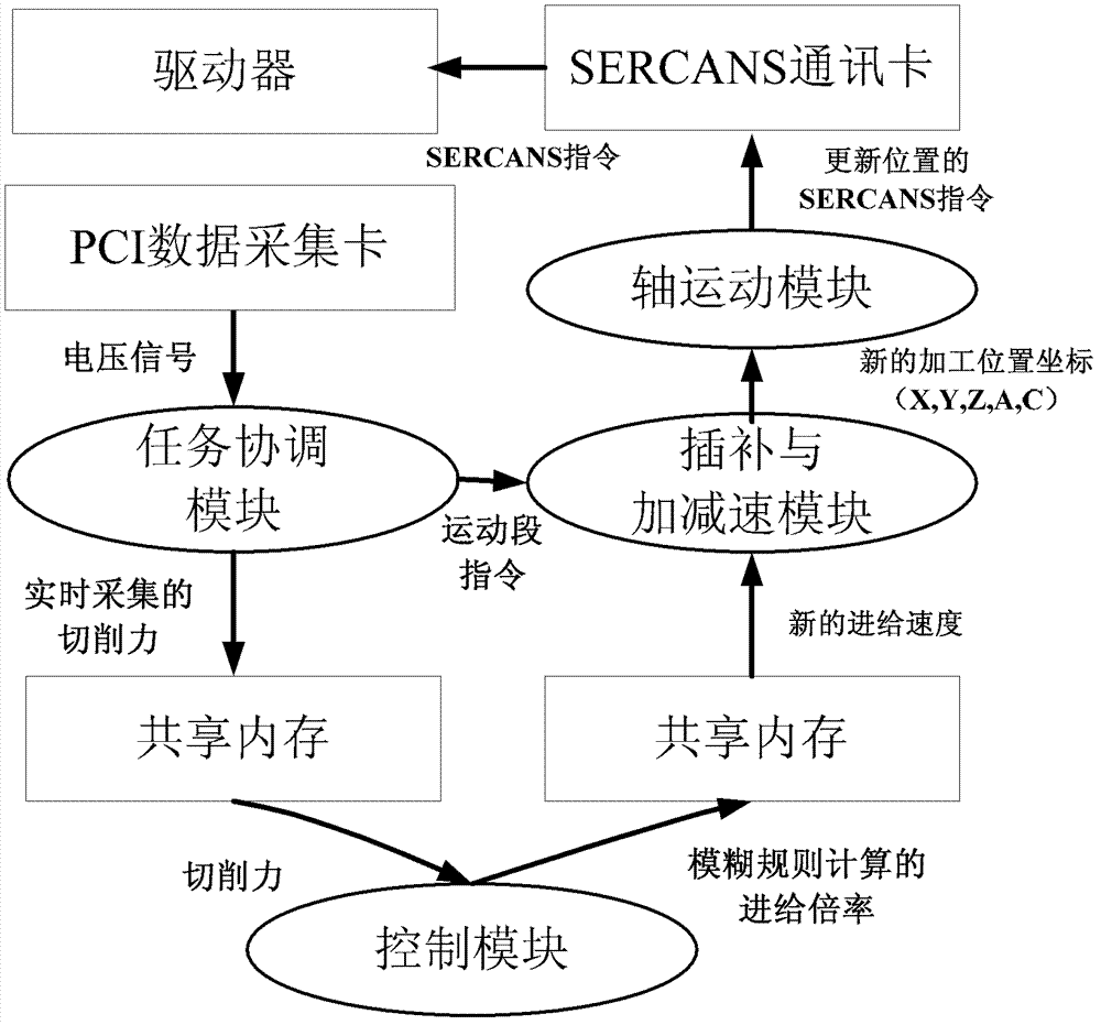
[0029] Specific implementation mode 1: the following combination figure 1 To explain this embodiment, the open intelligent milling processing system described in this embodiment includes a three-way piezoelectric force gauge sensor 1, an A / D conversion circuit 2, an industrial PC 3, a PCI data acquisition card 4, and a milling control Device 5, SoftSERCANS communication card 6, I / O module 7 and n servo drives 8, where n is a natural number greater than 1,

[0030] PCI data acquisition card 4, milling controller 5 and SoftSERCANS communication card 6 are set on industrial PC 3.

[0031] The three-way piezoelectric force gauge sensor 1 collects the cutting force generated by the interaction between the workpiece and the tool. The signal output terminal of the three-way piezoelectric force gauge sensor 1 is connected to the input terminal of the A / D conversion circuit 2. A / The output end of the D conversion circuit 2 is connected to the input end of the PCI data acquisition card 4, t...

specific Embodiment approach 2

[0036] Specific implementation manner 2: This implementation manner further illustrates the implementation manner. The three-way piezoelectric force gauge sensor 1 adopts the 9257B force gauge produced by Kistler.

specific Embodiment approach 3

[0037] Specific implementation manner 3: This implementation manner further illustrates the implementation manner 1. The PCI data acquisition card 4 adopts the PCI1710 data acquisition card produced by Taiwan Advantech.


PUM


Abstract

The invention relates to an open type intelligent milling system and a milling method based on the same, belonging to the field of machining and solving the problem of incapability of maintaining a processing target to be always optimal through offline optimized processing parameters in the traditional milling system for optimizing by adopting an offline algorithm. The open type intelligent milling system disclosed by the invention comprises a three-way piezoelectric type dynamometer sensor, an A / D (Analogue / Digital) conversion circuit, an industrial PC (Personal Computer), a PCI (Peripheral Component Interconnect) data acquisition card, a milling controller, an Soft SERCANS communication card, an input / output module and n servo drivers. The milling method disclosed by the invention comprises the following steps of: acquiring a cutting force generated by interaction between a work-piece and a cutter in real time; obtaining a feeding multiplying power by the milling controller so as toobtain a new feeding speed as the next feeding speed of the cutter; determining a next position of a machine tool; transmitting a position instruction to the corresponding servo drivers by the milling controller through the Soft SERCANS communication card and the input / output module so as to control the corresponding cutters to move; and realizing the intelligent control of the processing.

Description

Technical field [0001] The invention relates to an open intelligent milling processing system and a milling processing method based on the system, belonging to the field of mechanical processing. Background technique [0002] Realizing the automation and intelligence of the processing process has always been the two main goals of the development of modern manufacturing technology. In the traditional metal cutting process, in order to prevent overloading of the machine tool, protect the tool, and eliminate the influence of various uncertain factors, the cutting amount is often determined by checking the relevant machining process manual based on experience. In order to ensure the stability of the machining process, Often only key parameters (such as feed speed, spindle speed, etc.) are allowed to be set once. This prolongs the machining time, and the deformation of the tool due to the fluctuation of the cutting force, and the premature tool wear due to the cutting load, which red...

Claims


Application Information

Patent Timeline
Patent Type & Authority Patents(China)
IPC IPC(8): B23C1/00G05B19/4093
Inventor 富宏亚李茂月韩振宇邵忠喜韩德东胡泊
Owner HARBIN INST OF TECH
Why Eureka
Try Eureka