High-temperature liquid furnace slag conveying method using valve conveying device

A valve device and high-temperature technology, which is applied in the field of rotary sealing valves and rotary sealing valve devices, can solve the problems of small number of valve blades, poor sealing effect, and inability to meet the pressure and sealing output requirements of high-temperature slag, so as to reduce rotational frictional resistance and ensure Effect of sealing pressure and oil supply pressure

Active Publication Date: 2014-01-01
北京中冶设备研究设计总院有限公司
View PDF2 Cites 0 Cited by
  • Summary
  • Abstract
  • Description
  • Claims
  • Application Information

AI Technical Summary

Problems solved by technology

However, the sealing valves disclosed in the above-mentioned patents cannot meet the airtight input requirements of 1350°C-1700°C high-temperature liquid slag at the slag inlet of the blast furnace and converter slag processing device, and cannot meet the pressure-tight output requirements of the high-temperature slag at the outlet of the slag processing device. At the same time, due to the small number of valve blades in the existing valve structure, the sealing effect of the cylinder seal is poor, which cannot meet the requirements of the existing slag treatment device for the input and output of high-temperature slag
There is currently no rotary seal valve used in high temperature slag treatment equipment

Method used


Image

  • High-temperature liquid furnace slag conveying method using valve conveying device
  • High-temperature liquid furnace slag conveying method using valve conveying device
  • High-temperature liquid furnace slag conveying method using valve conveying device

Examples


Embodiment Construction

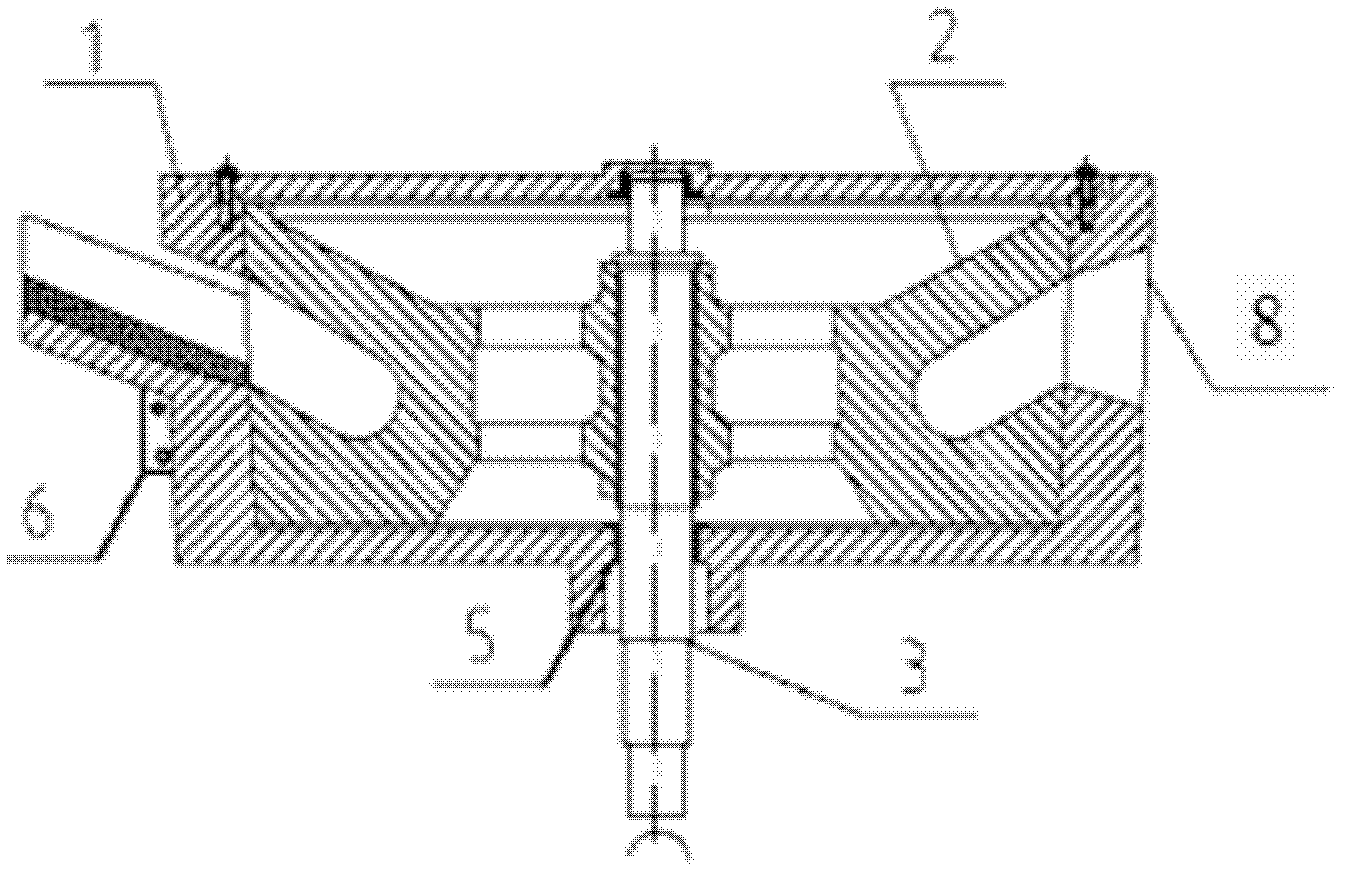
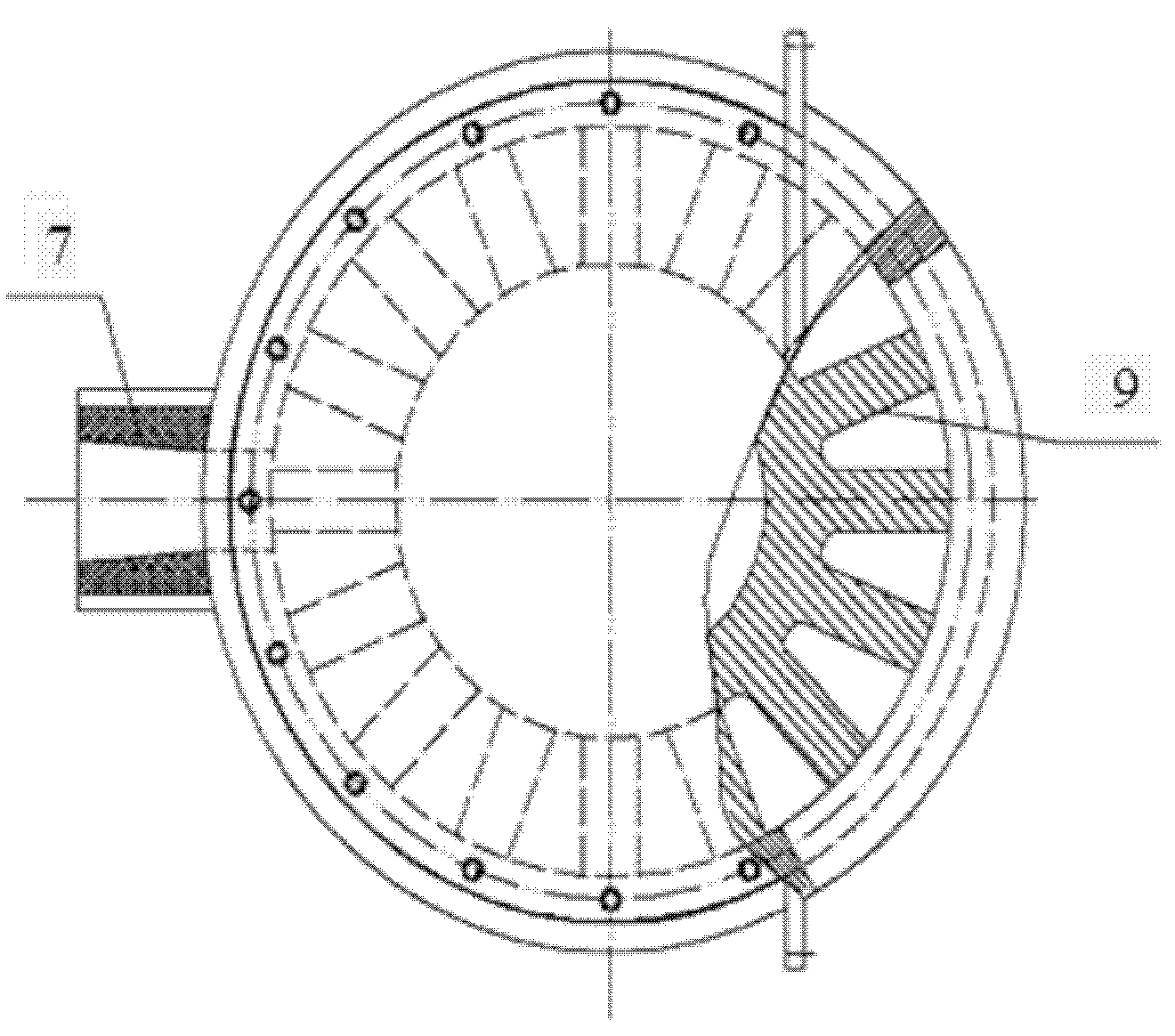
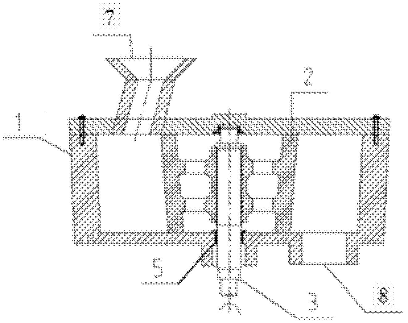
[0019] Embodiment 1~5 of the present invention will be described in further detail below in conjunction with accompanying drawing: Embodiment 1 is as follows: figure 1 , figure 2 The conveying valve device used in the method of conveying high-temperature liquid slag using the conveying valve device shown is mainly composed of a shell 1, an impeller 2, a shaft 3, a bearing 5, a water wall 6, a slag inlet 7, a slag outlet 8, Composed of blades 9, the shell 1 is subdivided into a slag inlet 7 and a slag outlet 8, the impeller is subdivided into a hub and 16 blades 9, the impeller is divided into 16 cavities by 16 blades 9, and the impeller 2 rotates It is installed in the shell 1 in a matching manner, the blade 9 forms a rotary seal with the shell 1, the upper part of the shell 1 is provided with an end cover, and the shell 1 is provided with a slag inlet 7 and a slag outlet 8 with a cooling wall 6, The stave 6 is installed on the outside of the slag inlet 7; the bearing 5 is i...


PUM


Abstract

The invention provides a high-temperature liquid furnace slag conveying valve device, which manly consists of a casing, an impeller, a shaft and a support seat and is characterized in that a slag outlet and a slag inlet with cooling walls are arranged on the casing, a bearing is arranged between the casing and the shaft, the impeller comprises a hub and blades and is divided into a plurality of hollow cavities by the blades, the impeller is arranged in the casing in a rotation matching way, the blades and the casing form the rotation sealing, a plurality of longitudinal and transverse lubricating oil hole passages and blowing hole passages are formed on the impeller and the casing, the furnace slag can adopt a side-inlet and side-outlet structure, an upper-inlet and lower-outlet structure and an upper inlet and side-outlet structure, and the sealing structure can be designed into a cylindrical surface sealing structure, a conical surface sealing structure and a plane sealing structure. A high-temperature liquid furnace slag conveying method is characterized in that high-temperature materials enter the device from the slag inlet and are output to the slag outlet by the sealing rotation of the blades to be rotatablely output. The high-temperature liquid furnace slag conveying valve device can be arranged at an inlet and an outlet of a high-temperature furnace slag processing device to be used as a feeding machine and a baiting valve, and the rotation sealing conveying of the high-temperature materials can be realized.

Description

Technical field: [0001] The invention relates to the technical field of iron-making and steel-making slag treatment, in particular to a rotary sealing valve used for the slag outlet and slag inlet of a blast furnace and converter slag treatment device, and a rotary sealing valve device and method for other input and output high-temperature material parts . Background technique: [0002] ZL200720200935.X utility model patent discloses a rotary feeding valve installed at the discharge port of the silo. Cover, there is an oil-soaked packing between the end cover and the intermediate shaft, and the sealing gland is placed on the outer end surface of the oil-soaked packing; there are bearings at both ends of the intermediate shaft; one end of the intermediate shaft is connected to the geared motor and the transmission mechanism . The utility model has uniform feeding, accurate quantification and good sealing. ZL200720090783.2 utility model patent discloses a rotary feeding val...

Claims


Application Information

Patent Timeline
Patent Type & Authority Patents(China)
IPC IPC(8): B65G29/00
Inventor 姜学仕姜宏泽
Owner 北京中冶设备研究设计总院有限公司
Why Eureka
Try Eureka