Screw lever type clamping mechanism

A clamping mechanism and lever-type technology, used in clamping, clamps, metal processing machinery parts, etc., can solve the problems of workpiece damage and low workpiece productivity, avoiding energy waste, convenient clamping and positioning, and firm structure. stable effect

Pending Publication Date: 2015-04-15
CHONGQING XIHUA BELT PULLEY MACHINERY MFG CO LTD
View PDF10 Cites 17 Cited by
  • Summary
  • Abstract
  • Description
  • Claims
  • Application Information

AI Technical Summary

Problems solved by technology

However, there is no mechanism on the clamping mechanism that can adjust the locking pressure. It is inevitable that the locking pressure will be too large during the locking process, which will damage the workpiece, resulting in some fragile and fragile parts. Workpiece productivity is low

Method used


Image

  • Screw lever type clamping mechanism
  • Screw lever type clamping mechanism

Examples


Embodiment Construction

[0014] The following further describes the present invention with reference to the drawings and embodiments, but it is not intended to limit the present invention.

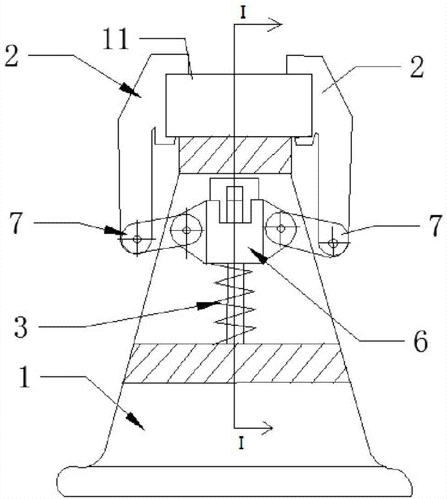
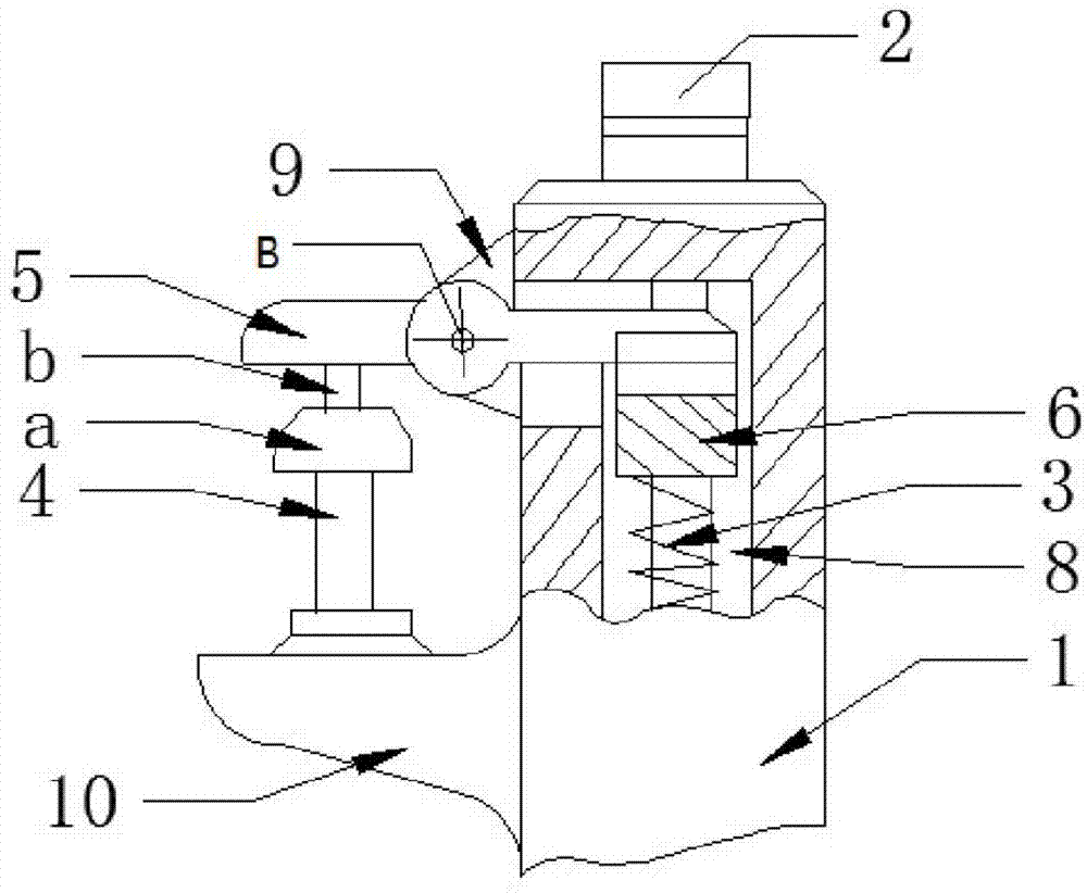
[0015] Such as figure 1 As shown, a screw lever type clamping mechanism includes a supporting table 1, a locking member and a driving member connected to the supporting table 1, and the supporting table 1 is an isosceles trapezoid, such as figure 2 As shown, one side of the support platform 1 is welded with a connecting plate 9 perpendicular to the ground and a support plate 10 parallel to the ground. A slide rail 8 is opened in the support platform 1, and the slide rail 8 is a vertical inverted L shape. Straight groove.

[0016] The driver includes a screw 4, a nut a, a cap b, a first lever 5, a first pin B, a first connecting member 6, a spring 3, and a second connecting member 7. The screw 4 is threadedly connected to the support On the plate 10, the screw 4 connects the nut a and the cap b, and the cap b is arran...


PUM


Abstract

The invention discloses a screw lever type clamping mechanism which comprises a supporting table, a locking part and a driving part. The supporting table is of an isosceles trapezoid structure, a connecting plate and a supporting plate are arranged on one side face of the supporting table, and a slide rail is arranged in the supporting table. The driving part comprises a screw, a nut, a cap-shaped object, a first lever, a first pin, a first connecting member, a spring and second connecting members, wherein the screw is connected to the supporting plate through threads, the nut and the cap-shaped object are connected to the screw, the cap-shaped object is arranged above the nut, the first lever is connected to the connecting plate through the first pin, one end of the first lever abuts against the cap-shaped object, the other end of the first lever abuts against the first connecting member, the first connecting member is in sliding connection with the slide rail, the left end and the right end of the first connecting member are respectively connected two second connecting members through pins, and the spring is connected between the first connecting member and the slide rail. The locking part comprises a clamping claw provided with a limiting groove, wherein the clamping claw is connected with the second connecting members through pins. The screw lever type clamping mechanism is firm in structure and adjustable in locking pressure.

Description

Technical field [0001] The invention relates to a clamping mechanism for clamping a workpiece, in particular to a screw lever type clamping mechanism. Background technique [0002] Clamping mechanism mainly includes screw clamping mechanism, pressure plate clamping mechanism, centering clamping mechanism, hinge clamping mechanism, lever clamping mechanism. In industrial production, in order to fix the workpiece for processing, it is often necessary to design some clamping mechanism. Commonly used clamping mechanisms include a supporting table, a locking member, and a driving member for driving the locking member. The locking member is driven by the driving mechanism to abut the workpiece against the support platform to fix the workpiece. However, there is no mechanism similar to the adjustable locking pressure on the clamping mechanism. It is inevitable that the locking pressure will be too large during the locking process, which will damage the workpiece, resulting in some fra...

Claims


Application Information

Patent Timeline
Patent Type & Authority Applications(China)
IPC IPC(8): B23Q3/06
CPCB23Q3/066B25B5/12
Inventor 唐建瑶
Owner CHONGQING XIHUA BELT PULLEY MACHINERY MFG CO LTD
Why Eureka
Try Eureka