

Clamping and pushing device of pipes
A technology for pushing devices and pipes, which is applied in auxiliary devices, laser welding equipment, auxiliary welding equipment, etc., and can solve problems such as inability to realize automatic feeding, lower transportation efficiency, and ineffective clamping
- Summary
- Abstract
- Description
- Claims
- Application Information
AI Technical Summary
Problems solved by technology
Method used
Image

Examples
Embodiment Construction
[0018] Specific embodiments of the present invention will be described in detail below in conjunction with the accompanying drawings.
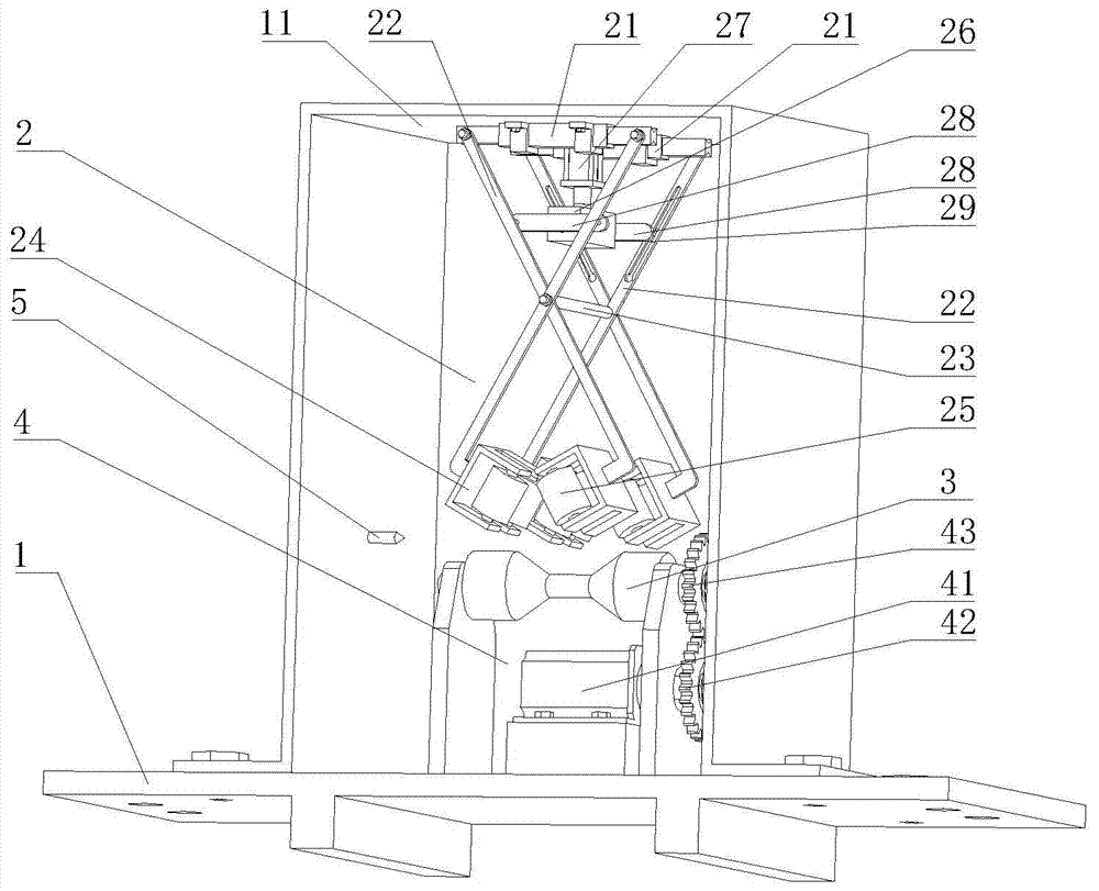
[0019] Such as figure 1 As shown, a pipe clamping and pushing device includes a mounting base 1, a top plate 11 is provided on the mounting base 1, a clamping centering mechanism 2 is provided on the lower surface of the top plate 11, and the mounting base 1 is below the centering clamping mechanism. The activity is provided with the feed roller 3 of colloid and the power mechanism 4 that drives the feed roller 3 . The feeding roller 3 includes a mounting portion, a loading portion with a diameter smaller than the mounting portion, and a conical transition section connecting the mounting portion to the loading portion. The power mechanism 4 includes a driving gear 42 driven by a servo motor 41 arranged on the mounting base 1 , and a driven gear 43 connected with the feeding roller 3 , and the driving gear 42 and the driven gear 43 are meshed....
PUM
 Abstract
Description
Claims
Application Information