Wear-resistant structure of circular needle cylinder

A needle cylinder and circular technology, applied in knitting, weft knitting, textiles and papermaking, etc., can solve the problems of needle cylinder wear, product cost increase, unevenness, etc., to improve service life, fabric quality assurance, weaving smooth effect

Inactive Publication Date: 2012-06-20
洪荣豪
View PDF11 Cites 6 Cited by
  • Summary
  • Abstract
  • Description
  • Claims
  • Application Information

AI Technical Summary

Problems solved by technology

[0005] 1. The knitting needle reciprocates under the drive of the knitting needle triangle. Due to the traction force of the cloth surface, the knitting needle will form continuous friction with the surface of the mouth of the needle cylinder, and the mouth of the needle cylinder and the bottom surface of the knitting needle will be worn due to friction, resulting in fit Errors in the accuracy will affect the quality of the final cloth weaving, which will easily lead to uneven density, wrinkling, and unevenness of the cloth weaving.
[0006] 2. Although the hardness of the syringe can be enhanced by heat treatment, the heat treatment process is complicated and the operation is troublesome, resulting in an increase in product cost
In addition, even if the nozzle of the needle cylinder is heat-treated to enhance its hardness, the heat treatment of the needle cylinder is likely to cause destructive wear to the needle cylinder itself

Method used


Image

  • Wear-resistant structure of circular needle cylinder
  • Wear-resistant structure of circular needle cylinder
  • Wear-resistant structure of circular needle cylinder

Examples


Embodiment Construction

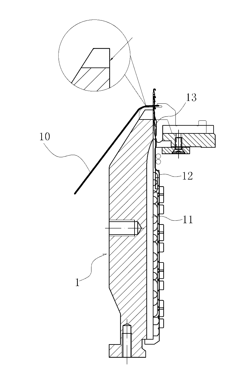
[0029] The technical solution adopted in the present invention is: an annular groove is provided near the mouth of the needle cylinder, and a wear-resistant steel wire is installed in the groove, and the wear-resistant steel wire forms frictional contact with the knitting needles to protect the needle cylinder and prevent wear and tear. . In the present invention, the syringe can be in various styles and models, which will be described with specific examples below.

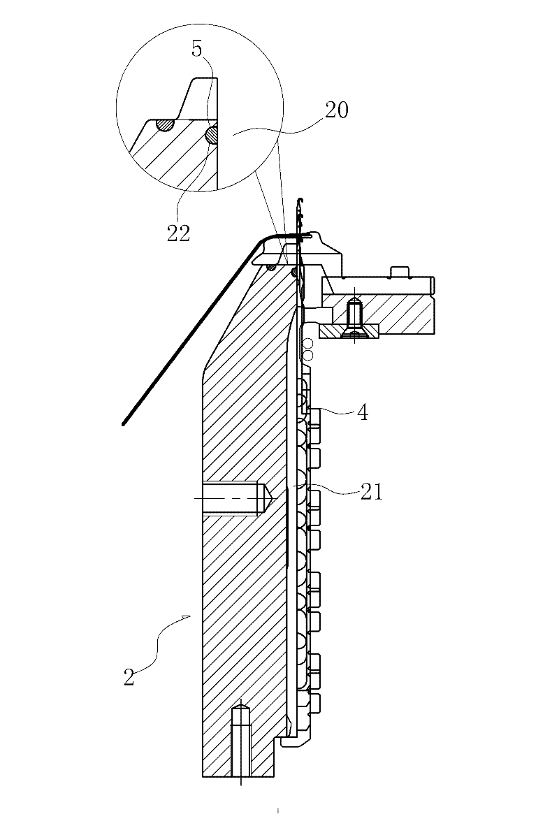
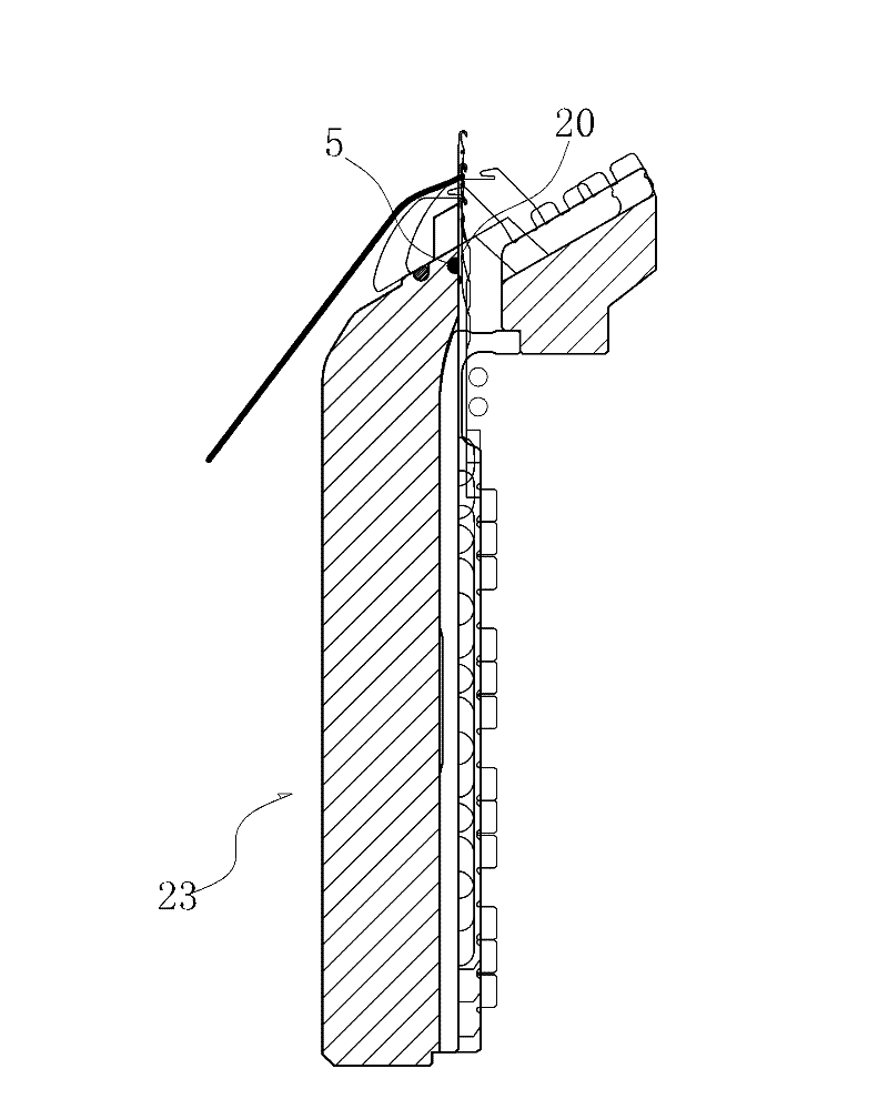
[0030] See figure 2 As shown, the first embodiment is a conventional vertical syringe 2 . The circumferential surface of the vertical needle cylinder 2 is vertically provided with a needle groove 21 for accommodating the knitting needle 4, and an annular groove 22 is provided on the surface above the needle groove 21 near the mouth of the needle cylinder 20. The annular groove 22 Along the peripheral surface of the vertical syringe 2, a wear-resistant steel wire 5 is arranged in the groove 22. The hardness of ...


PUM


Abstract

The invention relates to the technical field of knitting machines, in particular to a wear-resistant structure of a circular needle cylinder. The wear-resistant structure comprises a needle cylinder, wherein a needle groove for containing a knitting needle is formed on the surface of the needle cylinder; a ring-shaped groove is formed in the position near the mouth of the needle cylinder; a wear-resistant wire is installed in the groove; and the knitting needle in the needle groove rubs with the wire in the reciprocation process. The wear-resistant structure has the following beneficial effects: the groove is formed in the position near the mouth and the ring-shaped wear-resistant wire is arranged in the groove, thus ensuring the unity of the hardness of the mouth of the needle cylinder and the hardness of the knitting needle; generally, the hardness of the wire is higher than that of the knitting needle, thus avoiding wear for a long time; when the knitting needle is used for knitting, wear of the mouth caused by stressed knitting can be completely eradicated; and besides, after the wear-resistant structure is adopted, smoother knitting of the knitting needle can be ensured, so that the quality of the knitted cloth cover is ensured and the service life of the needle cylinder is further prolonged.

Description

Technical field: [0001] The invention relates to the technical field of knitting machines, in particular to a wear-resistant structure of a circular needle cylinder. Background technique: [0002] Circular knitting machines (or knitting machines) have a circular needle cylinder, see figure 1 As shown, this needle cylinder 1 is called cylindrical, and its outer peripheral surface is uniformly provided with needle grooves 11 for accommodating knitting needles. Realize running up and down. When the knitting needle 12 is running up and down, the knitting needle hook above it stretches out the mouth 13 of the needle cylinder 1, hooks the thread running here, and performs the knitting operation. [0003] Such as figure 1 As shown, during the continuous weaving process of the knitting needles 12, the cloth surface 10 formed by weaving will continue to run downwards. Due to the traction process of the cloth surface 10, a certain traction force will be formed on the knitting needl...

Claims


Application Information

Patent Timeline
Patent Type & Authority Applications(China)
IPC IPC(8): D04B15/14
Inventor 洪荣豪
Owner 洪荣豪
Why Eureka
Try Eureka