LED light bar

A technology of LED light strips and light panels, applied in the field of lighting, can solve the problems of heat dissipation, light efficiency and waterproof, cleanliness needs to be improved, reduce the heat dissipation performance of the heat sink 110, limit the overall light efficiency of LED light strips, etc., to improve self-adaptation Cleaning performance, lateral width reduction, effects of pressure loss avoidance

Inactive Publication Date: 2013-09-04
苏睿
View PDF1 Cites 1 Cited by
  • Summary
  • Abstract
  • Description
  • Claims
  • Application Information

AI Technical Summary

Problems solved by technology

Because the LED light source is located in the depth of the fixed groove 111, the groove wall limits the irradiation angle of the LED light source, so the irradiation angle of the entire light bar 10 is greatly limited, and the planar shape of the light outlet cover 14 has a great impact on the LED light source itself. The angle of illumination has little effect, which limits the overall light effect of the LED strip
[0007] In terms of cleaning, since the cooling groove 110 is completely located on the upper end area of ​​the fixing groove 111, the longitudinal cooling grooves 113 on both sides of the fixing groove 111 surround the whole cooling groove 110 into a bottom closed groove area, so that the inside of the cooling groove 110 Dust and other impurities are not easy to be washed away by rainwater, and long-term accumulation will reduce the heat dissipation performance of the heat sink 110, and even affect the life of the light source
[0008] Generally speaking, in the technical solution disclosed in the above patent application, the light bar is a popular form used in various types of LED lamps today, and the parallel light bar setting method is the trend of current LED lamps, but its heat dissipation, light effect and Waterproof and cleanliness need to be improved

Method used


Image

  • LED light bar
  • LED light bar
  • LED light bar

Examples


Embodiment

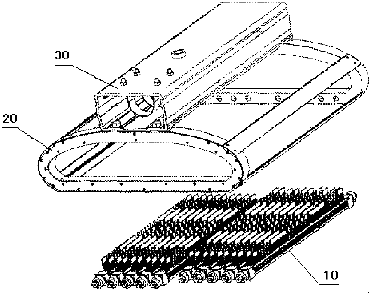
[0049] Such as Figure 4 , 5 As shown, the LED light bar of the present invention includes a heat dissipation bracket 201 , a light board 202 on which an LED light source 204 is fixed, and a semicircular light output cover 203 .

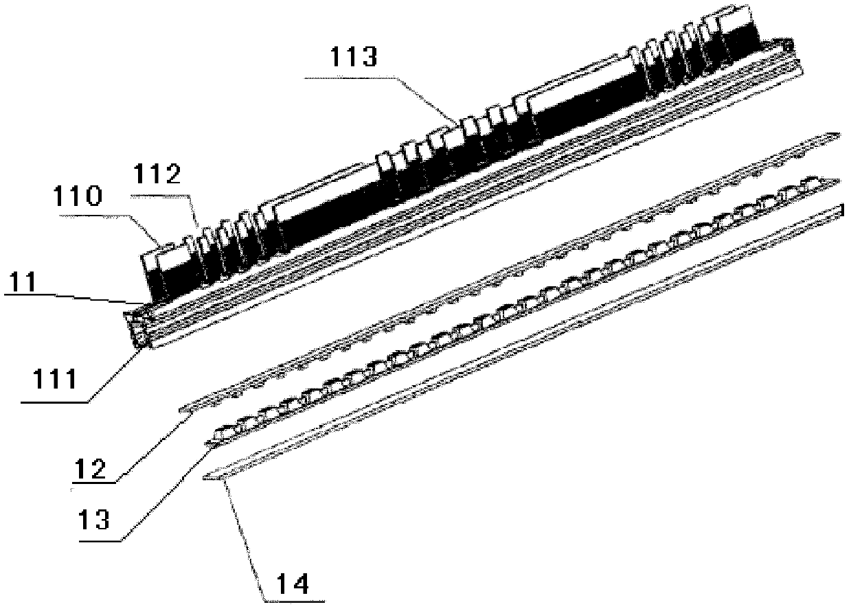
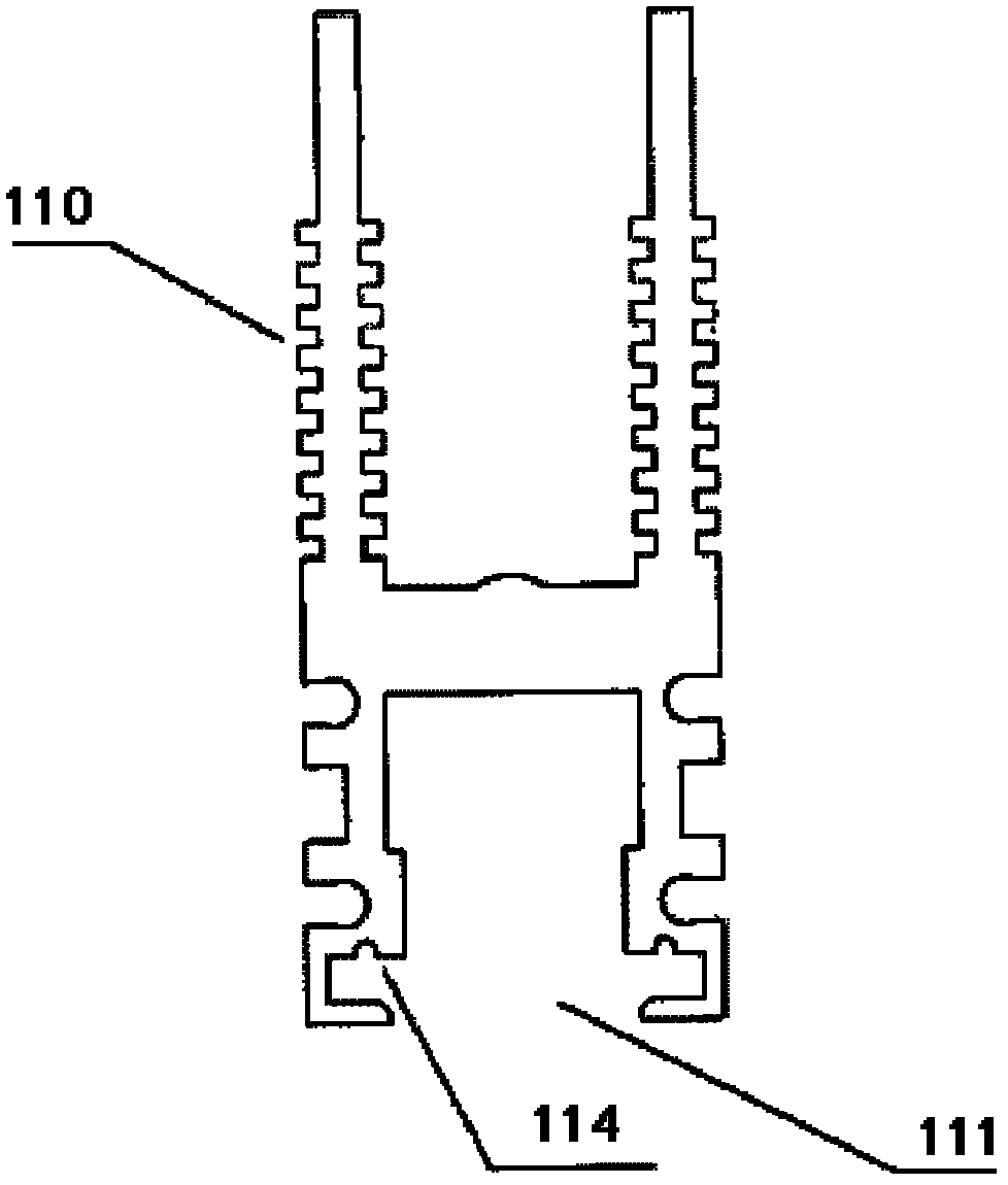
[0050] Such as Figure 6 As shown, the heat dissipation bracket 201 includes a heat dissipation groove 205 and a fixing bar 206. The heat dissipation groove 205 and the fixing strip 206 are designed in an integrated manner, and are made of a mixture of rare earth and aluminum, specifically composed of the following components by mass percentage:

[0051] Mg 0.4%~1%,

[0052] Si 0.7%~18%,

[0053] Mn 0.12%~0.2%,

[0054] Cr 0.12%~0.2%,

[0055] Cu 0.12%~0.2%,

[0056] Fe 0.12%~0.2%,

[0057] Ti 0.12%~0.2%,

[0058] Re 0.1%~0.2%,

[0059] Al balance.


PUM


Abstract

The invention provides an LED light bar. The LED light bar is provided with a radiating bracket, wherein the radiating bracket comprises a radiating groove and a fixing strip which are designed integrally; the fixing strip is used for connecting the radiating bracket with a light panel; the radiating groove adopts a shovel teeth-type radiating fin and is a transversal radiating groove; and the transversal width of the shovel teeth-type radiating fin is larger than that of the fixing strip, so that the part of the transversal radiating groove, which exceeds the fixing strip in the width direction, is hollowed out. As the part of the transversal radiating groove, which exceeds the fixing strip in the width direction, is hollowed out, the LED light bar has the advantages that on one hand, the heat quantity of the fixing strip can be transferred to the whole radiating groove, except the part of the radiating fin right above the fixing strip, the hollowed out part of the radiating fin can take part in conducting the heat quantity of the fixing strip, and the hollowed out area can obtain external air to form natural upward air convection; on the other hand, the radiating groove, which is completely transversal, is greatly reduced in transversal width while being compared with a longitudinal radiating groove, so that the radiating rate is higher. Moreover, the hollowed out part of the radiating groove can guide rainwater out fast.

Description

technical field [0001] The invention relates to the technical field of lighting, in particular to an LED light bar. Background technique [0002] As the fourth-generation lighting source, LED is more and more well-known, and its advantages of energy saving and environmental protection are particularly prominent in the field of indoor and outdoor lighting. It can be known from many LED application schemes that LED light sources are widely used in outdoor street lights, tunnel lights, and indoor lights in the form of light bars, and the key technical indicators of LED light bars are heat dissipation, light efficiency, and waterproof and clean. [0003] Such as the current high-power LED street lamp, its more advanced technical solution adopts the parallel design of multiple light bars. For example, the application date is October 26, 2009, and the Chinese invention patent application number 200910110334.3 discloses a technical solution for LED street lamps, which includes at ...

Claims


Application Information

Patent Timeline
Patent Type & Authority Patents(China)
IPC IPC(8): F21S4/00F21V29/00F21V3/02F21V19/00F21Y101/02F21S4/28F21V29/74F21V29/83F21V29/89F21Y115/10
Inventor 苏睿
Owner 苏睿
Why Eureka
Try Eureka