Installing structure of guardrail lamp

A technology for installation structures and guardrail lights, which is applied in the direction of lighting devices, fixed lighting devices, lighting device components, etc., can solve problems such as inability to cooperate with installation, rework and redo, and inaccurate positioning holes, so as to avoid installation deviation, Accurate positioning, simple operation effect

Active Publication Date: 2015-06-17
SHANGHAI SANSI ELECTRONICS ENG +3
View PDF8 Cites 1 Cited by
  • Summary
  • Abstract
  • Description
  • Claims
  • Application Information

AI Technical Summary

Problems solved by technology

This kind of installation structure is bound to have inaccurate correspondence between the positioning holes of the two, which can easily cause installation deviations. In severe cases, even the two cannot be installed together, and the problem of rework and redo
In order to solve this problem, a method of setting chutes in the structure connecting the lamps and guardrails is also widely used in the industry, such as the technical solution disclosed in the patent application document with the publication number CN201779556, and this technical solution , although it can solve the installation error in the axial direction of the guardrail, it cannot solve the installation problem caused by the section direction of the guardrail

Method used


Image

  • Installing structure of guardrail lamp
  • Installing structure of guardrail lamp
  • Installing structure of guardrail lamp

Examples


Embodiment Construction

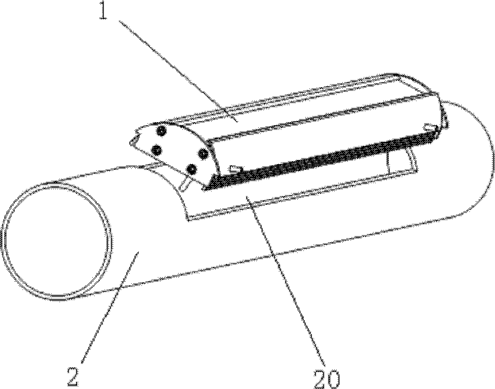
[0023] Such as figure 1 As shown, the guardrail light installation structure disclosed in the present invention includes a lamp 1, which is installed in a long slot 20 opened on the cylindrical wall of the cylindrical guardrail 2.

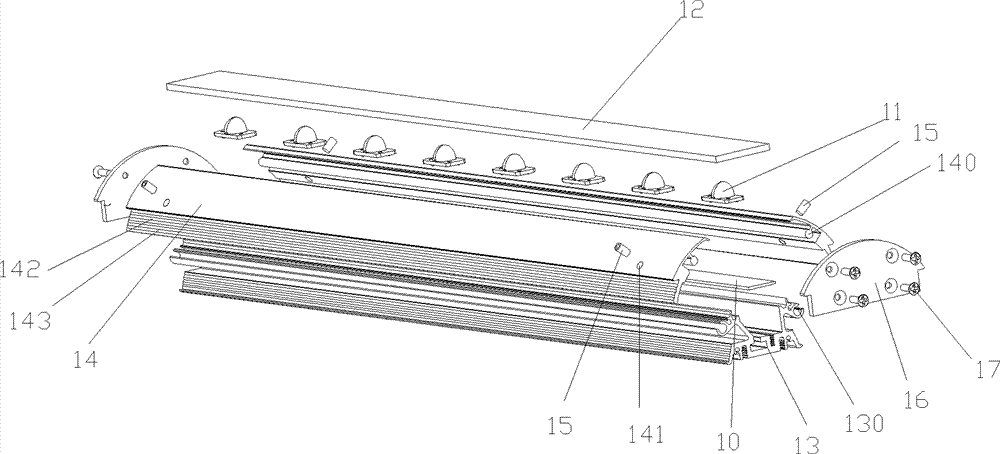
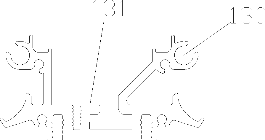
[0024] Such as Figure 2 ~ Figure 6 As shown, the lamp 1 is composed of a display part and an installation part. The display part includes a circuit board 10 on which a number of LED light sources 11 are mounted, and a mask 12 is placed at the light outlet. The mounting part of the luminaire 1 is a fixed bracket 13 made of a slotted aluminum alloy profile. On both sides of the fixed bracket 13, connecting pieces 14 are installed. The connecting pieces 14 are two arc-shaped aluminum alloy profiles. There is a round shaft 140, which penetrates into the arc-shaped sliding groove 130 provided on both sides of the fixed bracket 13, and the round shaft 140 can slide and rotate in the sliding groove 130. A through hole 141 is opened on the surface of the con...


PUM


Abstract

The invention relates to an installing structure of a guardrail lamp, which comprises a lamp, wherein the lamp is installed in an elongated slot arranged on a cylindrical guardrail. The lamp comprises a display panel and a fixing bracket for installing the display panel, wherein the fixing bracket is a section bar, the middle is provided with a slot, connecting components are installed on the slot walls of both sides, the connecting components are arc-shaped section bars, the inner sides of the connecting components are provided with circular shafts, and the circular shafts penetrate into circular arc-shaped sliding slots arranged at both sides of the fixing bracket; moreover, the circular shafts can rotate in the sliding slots so as to drive the connecting components to realize side turning within a certain angle relative to the fixing bracket; the surfaces of the connecting components are provided with through holes, and screws are installed in the through holes; and one ends of the screws are supported on the fixing bracket by rotating the screws, and the screws are continuously rotated until the parts of the outer edges of the connecting components are in side turning to positions where the parts of the outer edges and the inner side wall of the guardrail are tightly jointed with the inner side wall of the guardrail, so that the lamp is fixed on the guardrail. According to the installing structure of the guardrail lamp, which is provided by the invention, the goal of accurate positioning and installing between the lamp and the guardrail can be achieved; and moreover, the structure is simple, and the operation is very convenient.

Description

Technical field [0001] The invention relates to a lamp, and further relates to a slotted cylindrical guardrail light installation structure. Background technique [0002] Guardrail lights usually refer to lamps installed on a slotted cylindrical guardrail. How to install the lamp on the guardrail, the common structure is to reserve positioning holes at the relative position of the guardrail and the lamp, and then use bolts to pass through the positioning holes to fix the two. This kind of installation structure is bound to have inaccurate correspondence between the positioning holes of the two, and it is easy to cause the installation to deviate. In severe cases, the two cannot be installed together and the problem is reworked. In order to solve this problem, a method of arranging a chute in the structure connecting the lamp and the guardrail is also widely used in the industry. For example, the technical solution disclosed in the patent application document with the publication...

Claims


Application Information

Patent Timeline
Patent Type & Authority Patents(China)
IPC IPC(8): F21S8/00F21V17/12F21W111/08
Inventor 王化锋曲长江成国庆陈琮
Owner SHANGHAI SANSI ELECTRONICS ENG
Why Eureka
Try Eureka