Fan shell injection molding equipment and method of automatically embedded copper piece

A technology for injection molding equipment and copper parts, which is applied in the field of fan casing injection molding equipment and injection molding for automatically embedded copper parts. , the effect of reducing labor intensity and stable production cycle

Pending Publication Date: 2022-01-28
苏州博宇科技有限公司
View PDF7 Cites 0 Cited by
  • Summary
  • Abstract
  • Description
  • Claims
  • Application Information

AI Technical Summary

Problems solved by technology

[0003] At present, the injection molding method of manually embedding copper parts may have the following problems: firstly, the lower shell products with missing copper parts flow to the customer, causing customers to be unable to use and complain seriously; secondly, the mold is crushed by the mold due to insufficient copper parts , and the time used for each mold is different during manual embedding, resulting in different plastic particle melting time for each mold product, resulting in unstable product size and deformation, and the final product assembly effect is different. During the work process, the operator It can only be operated standing up, and the production efficiency is low. The general production cycle is between 45 seconds and 55 seconds
However, it does not mention how to ensure the vertical embedding of copper parts before injection molding, and misalignment and deviation will inevitably occur during the installation process

Method used


Image

  • Fan shell injection molding equipment and method of automatically embedded copper piece
  • Fan shell injection molding equipment and method of automatically embedded copper piece
  • Fan shell injection molding equipment and method of automatically embedded copper piece

Examples


Embodiment Construction

[0053] In order to make the purpose and technical solutions of the embodiments of the present invention more clear, the technical solutions of the present invention will be clearly and completely described below in conjunction with the embodiments of the present invention.

[0054] In the description of the present application, it is to be understood that the terms "length", "upper", "lower", "vertical", "horizontal", "top", "bottom", "inner", "outer", The orientation or positional relationship indicated by etc. is based on the orientation or positional relationship shown in the drawings, which is only for the convenience of describing the application and simplifying the description, rather than indicating or implying that the referred device or element must have a specific orientation, use a specific Azimuth configuration and operation, therefore, should not be construed as limiting the application.

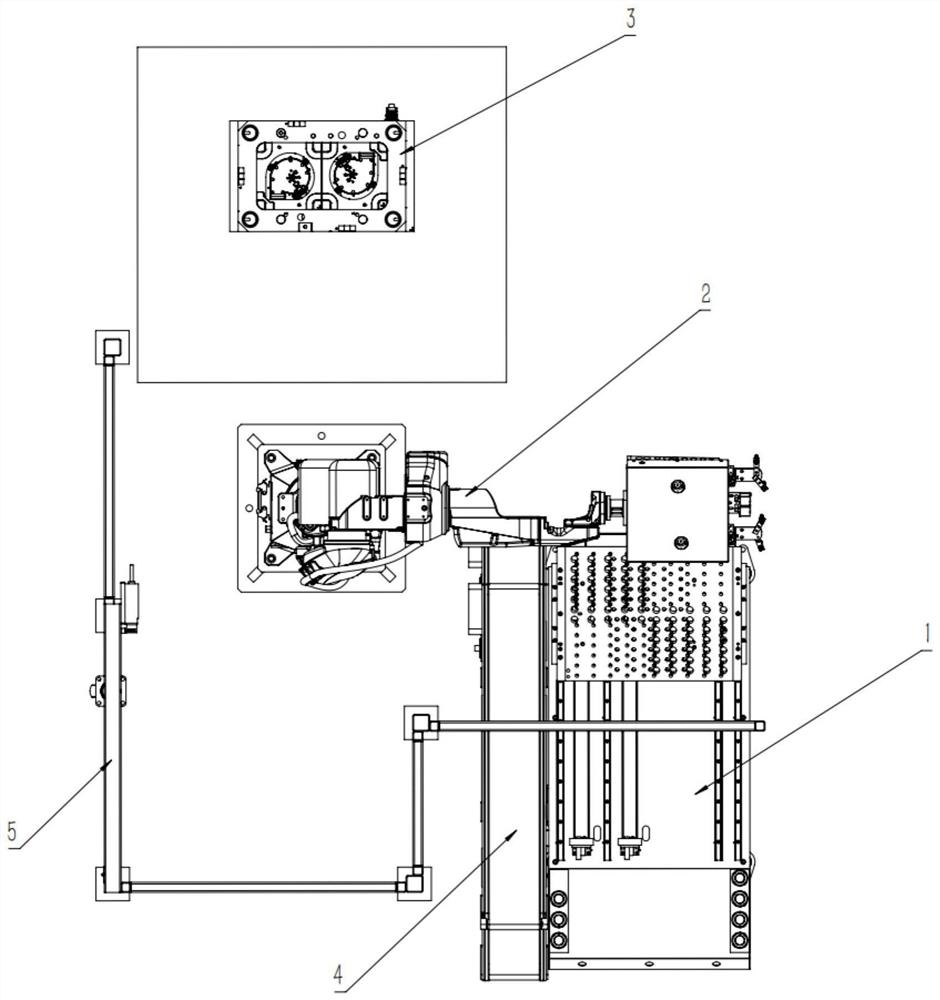
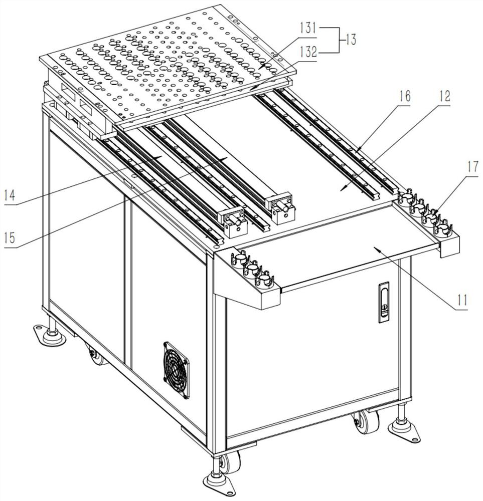
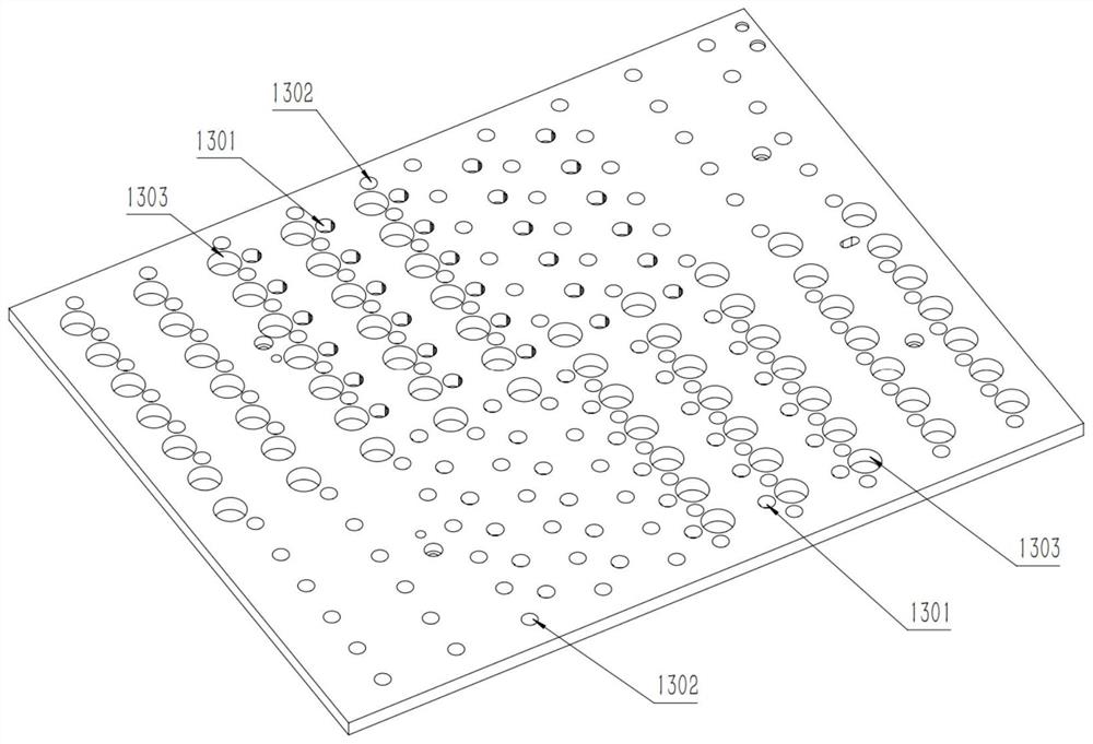
[0055] A blower casing injection molding equipment for automatically embedd...


PUM


Abstract

The invention provides (a) fan shell injection molding equipment and method of an automatically embedded copper piece, and relates to the technical field of fan shell injection molding. The fan shell injection molding equipment comprises a feeding system, a carrying system, an injection molding system and a discharging system, the feeding system comprises a material placing area, a workbench and a material sliding table plate; a plurality of materials can be placed on the material sliding table plate; the carrying system comprises a mechanical arm, a multifunctional clamping jaw is arranged at the tail end of the mechanical arm, the multifunctional clamping jaw comprises a base plate, and two material clamping devices are fixed to the base plate; a plurality of positioning columns are distributed on the lower surface of the base plate, and two mold locking devices are arranged on the lower surface of the base plate; the multifunctional clamping jaw achieves reciprocating carrying among the feeding system, the injection molding system and the discharging system; and the injection molding system comprises an injection mold, and the upper surface is further provided with a positioning hole and a mold locking groove. According to the technical scheme, the installation precision of the copper piece is high, the phenomenon that the surface is scratched due to installation inclination is avoided, and the product precision and quality are guaranteed.

Description

technical field [0001] The invention relates to the technical field of blower casing injection molding, in particular to a blower casing injection molding equipment and an injection molding method for automatically embedding copper parts. Background technique [0002] Fan lower casing products include plastic parts, fans and copper parts necessary for motor stators. The commonly used method for producing lower casing products is injection molding. Injection molding is a molding mold widely used in the production of plastic parts. Injection molding is a tool for the complete structure and precise dimensions of the product. Injection molding is a processing method used in the mass production of certain complex-shaped parts. In the prior art, the production method of the lower shell product is generally as follows: ① manually put the copper parts into the injection mold; ② press the start button of the injection molding machine to close the mold manually; ③ re-injection molding...

Claims


Application Information

Patent Timeline
Patent Type & Authority Applications(China)
IPC IPC(8): B29C45/14
CPCB29C45/14065B29C45/14008
Inventor 彭寅
Owner 苏州博宇科技有限公司
Why Eureka
Try Eureka