
Resistance strain gauge paster compressing device with constant pressure

A technology of resistance strain gauge and pressing device, which is applied in electromagnetic measuring device, measuring device, electric/magnetic solid deformation measurement, etc., can solve the problems of difficulty in ensuring the constancy of the applied pressure, and the direction and position of the strain gage sticking. , to achieve good bonding effect

Inactive Publication Date: 2012-06-20
SHANGHAI APPLIED TECHNOLOGIES COLLEGE
View PDF5 Cites 7 Cited by
  • Summary
  • Abstract
  • Description
  • Claims
  • Application Information

AI Technical Summary

Problems solved by technology

Due to the manual operation, it is difficult to ensure the sticking direction and position of the strain gauge, and it is also difficult to ensure the constancy of the applied force.

Method used


Image

  • Resistance strain gauge paster compressing device with constant pressure
  • Resistance strain gauge paster compressing device with constant pressure

Examples


Embodiment Construction

[0011] The present invention will be further described below in conjunction with the accompanying drawings and embodiments.

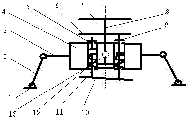
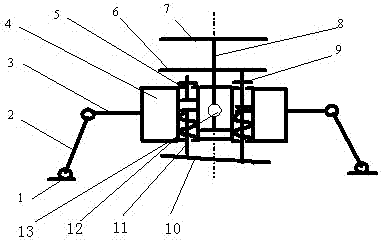
[0012] Such as figure 1 As shown, the resistance strain gauge patch pressing device with constant pressure of the present invention includes a magnetic suction seat 1, a longitudinal support bar 2, a transverse support bar 3, a female mounting block 4, pressing bars a5, b9, and an auxiliary pressing block 6 , Depress the handle 7, depress the handle connecting rod 8, rubber block 10, auxiliary pressing bar 11, pressing bar spring 12, locking screw 13, etc.

[0013] The two sides of the female block 4 are respectively connected to the magnetic suction seat 1 through the horizontal support rod 3 and the longitudinal support rod 2 in turn. The two mounting holes of the female block are respectively equipped with pressing rods a5 and b9, and the length of the pressing rod b9 is greater than The length of the pressure rod a5, the auxiliary pressure rod 11 i...


PUM


Abstract

The invention relates to a resistance strain gauge paster compressing block with constant pressure. Two sides of a mounting mother block are respectively connected with magnetic absorption seats by virtue of a transverse support rod and a longitudinal support rod sequentially, compression bars a and b are respectively arranged in two mounting holes of the mounting mother block, length of the compression bar b is more than the length of the compression bar a, an auxiliary compression bar is respectively arranged below the compression bars a and b, rubber blocks are respectively arranged below the auxiliary compression bars, a compression bar spring is arranged outside each auxiliary compression bar, a pressing handle connecting rod is arranged at the middle part of the mounting mother block, and a pressing handle and an auxiliary pressing block are arranged above the pressing handle connecting rod. Locking screws are arranged between the mounting mother block and the pressing handle connecting rod. By using the spring structure of the compressing device, the compressing device maintains a certain constant pressure all the time when a paster is compressed, and pasting direction and position can be observed, if an error is found in the pasting direction and position, the pasting direction and position can be timely adjusted, and excessive adhesive and air during pasting can be conveniently removed, thus the pasting effect is better.

Description

technical field [0001] The invention relates to a patching device for resistance strain gauges, in particular to a pressing device for patching resistance strain gauges. Background technique [0002] The resistance strain gauge is a commonly used stress and strain measuring element. The resistance strain gauge is used as the sensing element, and it is firmly pasted on the measuring point of the component. After the component is stressed, due to the strain of the measuring point, the strain gauge also follows The deformation of the strain gauge changes the resistance of the strain gauge, and then the resistance change of the strain gauge is measured by a special instrument, and converted into the strain value of the measuring point. The measurement principle of the resistance strain gauge is: the resistance value of the metal wire is not only related to the properties of the material, but also related to the length and cross-sectional area of ​​the metal wire. Paste the meta...

Claims


Application Information

Patent Timeline
IPC IPC(8): G01B7/16G01L1/22
Inventor 胡飒英石钢闫春晖
Owner SHANGHAI APPLIED TECHNOLOGIES COLLEGE
Learn More