Intelligent charging control circuit and intelligent charging control method

A control circuit, intelligent charging technology, applied in battery circuit devices, circuit devices, current collectors, etc., can solve the problems of charger confusion, not fully utilizing the charging capacity of the charger, exceeding the output capacity of the charger, etc.

Inactive Publication Date: 2012-06-20
GUANGDONG OPPO MOBILE TELECOMM CORP LTD
View PDF4 Cites 13 Cited by
  • Summary
  • Abstract
  • Description
  • Claims
  • Application Information

AI Technical Summary

Problems solved by technology

[0002]The existing charging circuit for electronic products basically sets a constant charging current according to the charger, such as 650mA for standard chargers, 500mA for USB PCs, 450mA for non-standard chargers, However, the chargers in the existing market are very confusing, and the current that standard chargers and non-standard chargers can provide is uncertain. If you simply set a charging current value, it may exceed the output capacity of the charger or not make full use of the charging capacity of the charger. ability

Method used


Image

  • Intelligent charging control circuit and intelligent charging control method
  • Intelligent charging control circuit and intelligent charging control method
  • Intelligent charging control circuit and intelligent charging control method

Examples


Embodiment Construction

[0021] The following will describe in detail with reference to the accompanying drawings in conjunction with the embodiments, so as to further explain the technical features and advantages of the present invention.

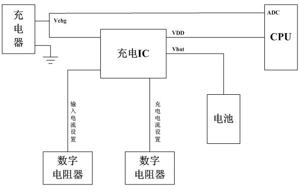
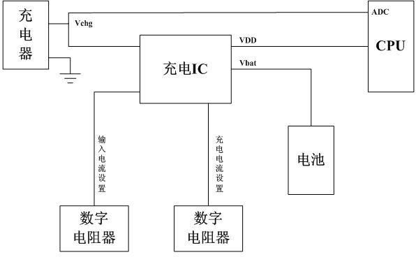
[0022] The principle block diagram of the present invention is as figure 1 As shown, an intelligent charging control circuit includes a charger and a battery, and the control circuit also includes a charging IC, a microcontroller CPU, an input current setting digital resistor and a charging current setting digital resistor, and the microcontroller CPU There is an ADC interface. One of the chargers is connected to the ADC interface of the microcontroller CPU, and the other is connected to the input terminal of the charging IC. The charging IC is respectively connected to the input current setting digital resistor and the charging current setting digital resistor. The charging IC The output end is connected with the battery, and the VDD interface of the microcontrol...


PUM


Abstract

The invention discloses an intelligent charging control circuit, which comprises a charger, a battery, a charging integrated circuit (IC), a central processing unit (CPU), an input current setting digital resistor and a charging current setting digital resistor, wherein an analog-to-digital conversion (ADC) interface is arranged on the CPU; one channel of the charger is connected with the ADC interface of the CPU, and the other channel of the charger is connected with an input end of the charging IC; the charging IC is respectively connected with the input current setting digital resistor and the charging current setting digital resistor; an output end of the charging IC is connected with the battery; and a voltage drain-drain (VDD) interface of the CPU is connected with the charging IC. The invention also discloses an intelligent charging control method. The invention has the advantages that: a Vchg voltage of a port of the charger is monitored through the ADC interface of the CPU, a charging current is adjusted in real time, and the output capacity of the charger can be fully utilized; and an input current limit which is set by the intelligent charging control circuit is prevented from exceeding the output capacity of the charger, damaging the charger and influencing operation of the whole circuit.

Description

technical field [0001] The invention relates to a charger control technology, in particular to an intelligent charging control circuit and a control method thereof. Background technique [0002] The existing charging circuit for electronic products basically sets a constant charging current according to the charger, such as 650mA for the standard charger, 500mA for the USB PC, and 450mA for the non-standard charger. The current that a standard charger can provide is uncertain. If you simply set a charging current value, it may exceed the output capacity of the charger or not fully utilize the charging capacity of the charger. Contents of the invention [0003] The purpose of the present invention is to overcome the deficiencies of the prior art and provide an intelligent charging control circuit and its control method, which can make full use of the output capacity of the charger and effectively protect the charger, the whole system and the battery. [0004] In order to a...

Claims


Application Information

Patent Timeline
Patent Type & Authority Applications(China)
IPC IPC(8): H02J7/00
Inventor 曾元清
Owner GUANGDONG OPPO MOBILE TELECOMM CORP LTD
Why Eureka
Try Eureka