Photovoltaic power generation unit power generation benefit maximization layout structure

A technology for photovoltaic power generation and layout structure, which is applied in photovoltaic power generation, photovoltaic power stations, photovoltaic modules, etc., and can solve the problem that photovoltaic modules cannot reach the rated output.

Active Publication Date: 2015-11-04
CHANGJIANG SURVEY PLANNING DESIGN & RES
View PDF3 Cites 0 Cited by
  • Summary
  • Abstract
  • Description
  • Claims
  • Application Information

AI Technical Summary

Problems solved by technology

However, from the analysis of actual operating conditions, photovoltaic modules with an installed capacity of 1MWp cannot reach the rated output of 1MWp, so the inverter operates with less than the rated power most of the time

Method used


Image

  • Photovoltaic power generation unit power generation benefit maximization layout structure
  • Photovoltaic power generation unit power generation benefit maximization layout structure
  • Photovoltaic power generation unit power generation benefit maximization layout structure

Examples


Embodiment Construction

[0024] The present invention will be further described in detail below in conjunction with the accompanying drawings, but this does not constitute a limitation to the present invention and is only an example. At the same time, the advantages of the present invention will become clearer and easier to understand.

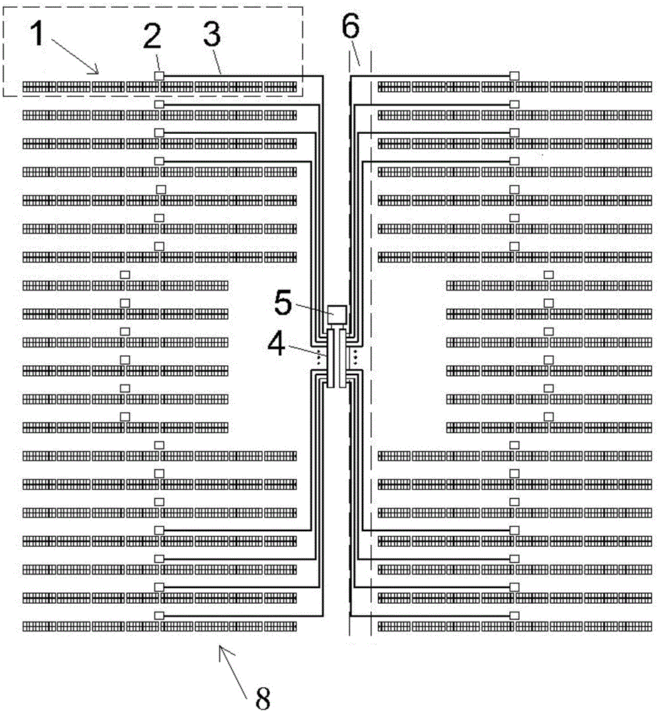
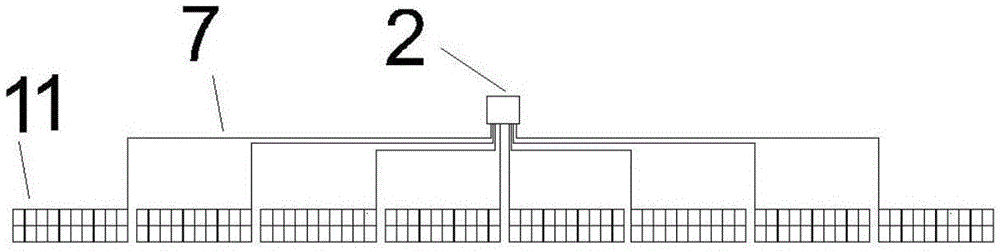
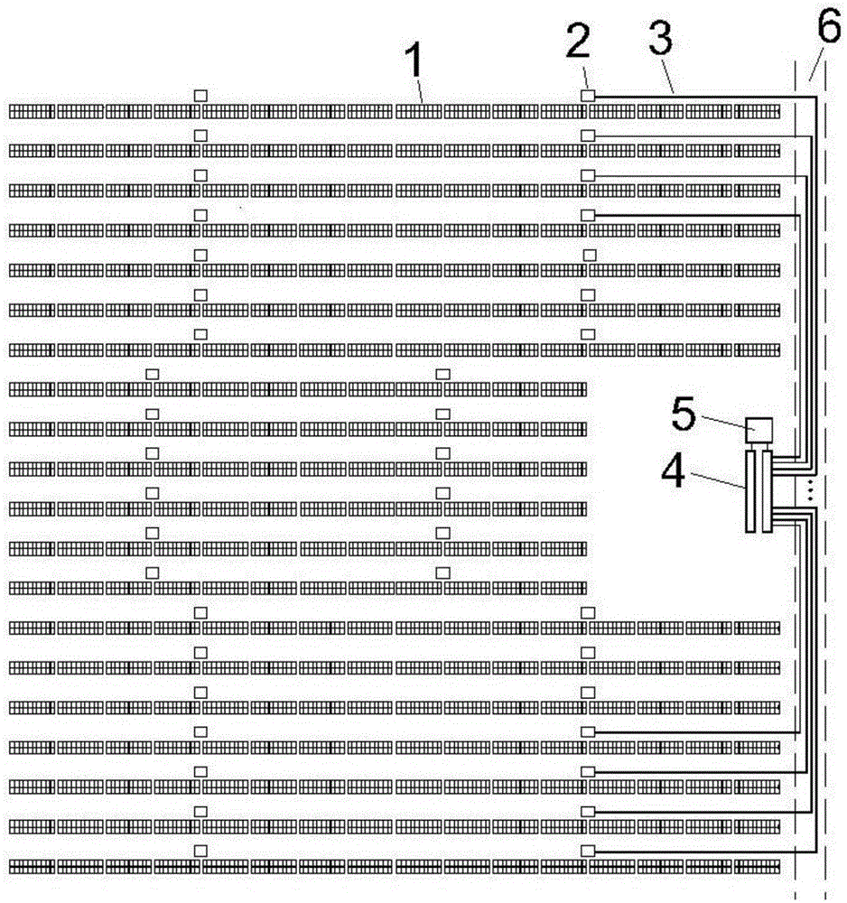
[0025] With reference to the drawings, it can be seen that the arrangement structure for maximizing the power generation efficiency of the photovoltaic power generation unit of the present invention is characterized in that it includes photovoltaic module strings 1 arranged in rows, and a combiner box 2 arranged in the middle of each row of photovoltaic module strings 1 in the same row Each photovoltaic module 11 is connected to the combiner box 2 through a primary bus cable 7, and a single combiner box 2 located in the middle position in front of each row of photovoltaic module string 1 is connected to the inverter 4 through a secondary bus cable 3. The row of photovolt...


PUM


Abstract

A maximum electricity benefit arrangement structure of photovoltaic power generation units comprises photovoltaic unit strings (1) arranged in rows and header boxes (2). The header boxes (2) are arranged in the front middle of each row of photovoltaic unit strings (1). Every one of photovoltaic units (11) in each row is connected with the corresponding header box (2) through a primary header cable (7). Every header box (2) in the front middle of each row of photovoltaic unit strings (1) is connected with an inverter (4) through a secondary header cable (3). The two inverters (4) are arranged on one side of a field region main way (6). Each inverter (4) is connected with half of photovoltaic power generation units (8) on the same side; the two inverters (4) are connected with a transformer (5). The inverters of the photovoltaic power generation units (8) are 1MW in total output power. The maximum electricity benefit arrangement structure has the advantage that maximum electricity benefit arrangement of the photovoltaic power generation units is achieved by comprehensively considering the factors, such as direct-current cable consumption, line loss, line voltage drop changes and inverter power output.

Description

Technical field [0001] The invention relates to photovoltaic power generation technology, in particular to an arrangement structure for maximizing power generation benefits of photovoltaic power generation units. Background technique [0002] A photovoltaic power generation unit is a basic organization in a photovoltaic power station. Usually each photovoltaic power generation unit is equipped with a transformer and several inverters. In actual projects, the photovoltaic installed capacity of a photovoltaic power generation unit is not fixed. Some photovoltaic power generation units are designed on a scale of 500kWp, and others are designed on a scale of 1MWp and 2MWp. Part of the research mentioned that the photovoltaic array should be arranged as rectangular as possible, but the reasonable layout of the inverter has not been analyzed. [0003] The overall layout of the photovoltaic power plant photovoltaic modules need to avoid being shaded by shadows as much as possible. There...

Claims


Application Information

Patent Timeline
Patent Type & Authority Patents(China)
IPC IPC(8): H02S10/00
CPCH02S10/00H02S40/00Y02E10/50
Inventor 赵鑫刘海波苏毅叶任时鱼维娜张鹏
Owner CHANGJIANG SURVEY PLANNING DESIGN & RES
Why Eureka
Try Eureka