Scanning bed

A technology of scanning bed and bed plate, applied in the field of scanning bed, can solve the problems of increased system complexity, difficult horizontal movement of bed plate, disadvantage, etc., and achieves the effects of simple control method, reduced structural complexity and manufacturing cost

Inactive Publication Date: 2012-06-27
SUZHOU INST OF BIOMEDICAL ENG & TECH
View PDF6 Cites 13 Cited by
  • Summary
  • Abstract
  • Description
  • Claims
  • Application Information

AI Technical Summary

Problems solved by technology

The existing CT (computer tomography, computed tomography) or (PEF/CTPositron Emission Computed Tomography, positron emission computed tomography) scanning bed's horizontal feed motion and vertical upgrade motion are independent of each other, powered by two power sources respectively, Its disadvantages are: at least two power sources and two control systems are required, and the complexity of the system increases, which is not conduc

Method used


Image

  • Scanning bed
  • Scanning bed
  • Scanning bed

Examples


Embodiment Construction

[0040] In order to make the object, technical solution and advantages of the present invention clearer, the present invention will be further described in detail below in conjunction with the accompanying drawings and embodiments. It should be understood that the specific embodiments described here are only used to explain the present invention, not to limit the present invention.

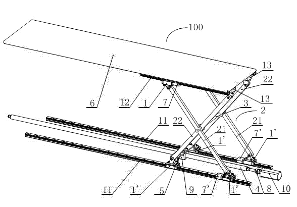
[0041] see figure 1 , the present invention provides a scanning bed 100, comprising:

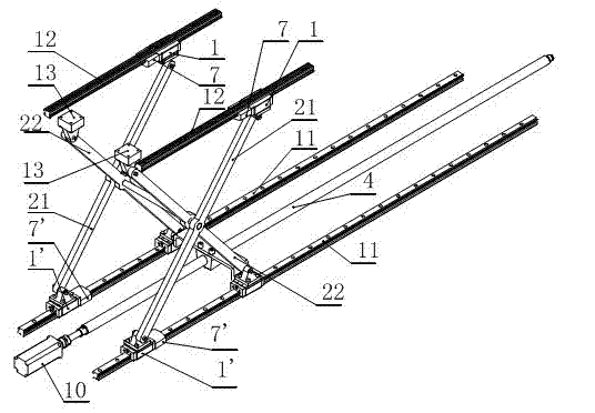
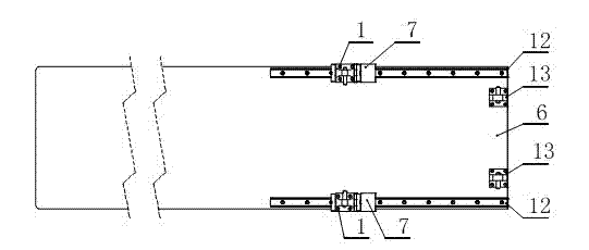
[0042] Two sets of linear guide rails 12, 11, including a first set of linear guide rails 12 and a second set of linear guide rails 11; the second set of linear guide rails 11 are arranged in parallel below the first set of linear guide rails 12;

[0043] The bed board 6 is fixedly connected to the first set of linear guide rails 12 on its lower end surface;

[0044] Sliding lifting mechanism, including the first group of guide rail sliders 1 and the second group of guide rail sliders 1'; th...


PUM


Abstract

The invention is suitable for the field of medical equipment, and provides a scanning bed which comprises two groups of linear guide rails, a bed plate, a sliding lifting mechanism and a power source, wherein the second group of linear guide rails is arranged below the first group of linear guide rails in parallel; the lower end face of the bed plate is fixedly connected with the first group of linear guide rails; a first group of guide rail brakes and a second group of guide rail brakes are respectively connected to the first group of linear guide rails and the second group of linear guide rails, a first group of guide rail sliders and a second group of guide rail sliders are respectively connected to the first group of guide rail brakes and the second group of guide rail brakes; the upper ends and lower ends of a first group of connecting rods of a scissor mechanism are respectively connected to the first group of guide rail sliders and the second group of guide rail sliders; the upper ends of a second group of connecting rods are fixedly connected to the lower end face of the bed plate, the lower ends of the second group of connecting rods are connected to the second group of guide rail sliders; a ball screw is parallel with the second group of linear guide rails, and a horizontal movement piece is connected with the second group of guide rail sliders and the ball screw; and the power source is connected to the head end of the ball screw. Therefore, the scanning bed provided by the invention achieves the purpose of providing power drive for a horizontal movement mechanism and a lifting mechanism of the scanning bed by only using one power source.

Description

technical field [0001] The invention relates to the field of medical equipment, in particular to a scanning bed. [0002] Background technique [0003] With the development of medical technology, more and more diseases can be realized through some scanning technologies. The existing CT (computer tomography, computed tomography) or (PEF / CTPositron Emission Computed Tomography, positron emission computed tomography) scanning bed's horizontal feed motion and vertical upgrade motion are independent of each other, powered by two power sources respectively, Its disadvantage is that at least two power sources and two control systems are required, and the complexity of the system increases, which is not conducive to reducing costs. However, if only one power source is used, it is impossible to provide power for two motion systems. [0004] For example, in the prior art, there is such an invention patent application. In the invention patent application number CN200810228504.3, the...

Claims


Application Information

Patent Timeline
IPC IPC(8): A61B6/04
Inventor 高飞刘岿
Owner SUZHOU INST OF BIOMEDICAL ENG & TECH
Why Eureka
Try Eureka