
Hydraulic compacting device

A compression device and oil pressure technology, applied in the direction of positioning device, clamping, support, etc., can solve the problems of long time required and slow movement speed, etc., and achieve easy control, shorten adjustment time, and fast compression Effect

Inactive Publication Date: 2012-06-27
常州市永益工具有限公司
View PDF5 Cites 8 Cited by
  • Summary
  • Abstract
  • Description
  • Claims
  • Application Information

AI Technical Summary

Problems solved by technology

[0003] The traditional vise drives the slider to slide through the screw rod, so as to realize the compression of the workpiece. The traditional vise has a large stroke and a wide range of applications, but there are also certain defects. Because it uses screw drive , which drives the slider to move at a slower speed, and when it is adjusted from the maximum stroke to the pressed state, it takes more time

Method used


Image

  • Hydraulic compacting device
  • Hydraulic compacting device

Examples


Embodiment Construction

[0011] The present invention will be further described below in conjunction with accompanying drawing;

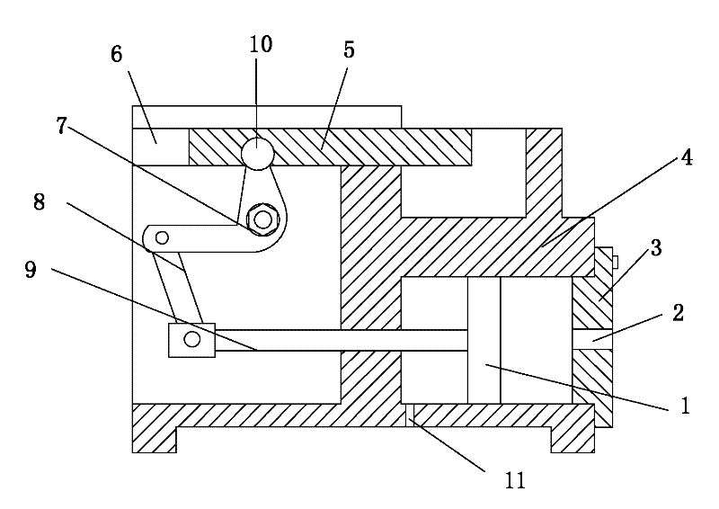
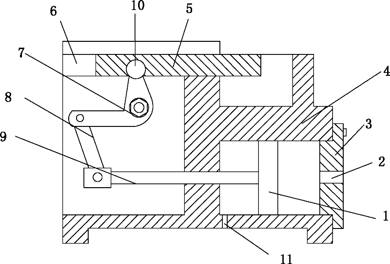
[0012] Such as figure 1 The hydraulic pressing device shown includes a base body, a hydraulic cavity is provided on the lower right side of the base body 4, and a cover plate 3 for sealing the hydraulic cavity, and the cover plate 3 is provided with a further Oil port 2, under the base body 4, there is an oil drain port 2 communicating with the hydraulic chamber. A piston 1 is arranged in the hydraulic chamber, and a piston rod 9 protruding from the hydraulic chamber is connected to the piston 1. The chute on the top of the base body 4 6. A sliding pressure plate 5 is arranged in the chute 6, and the piston rod 9 is connected with the pressure plate 5 through a linkage mechanism.

[0013] The linkage mechanism includes an L-shaped transmission rod 7 connected to the base body through a rotating shaft, one end of the L-shaped transmission rod 7 is connected to the slide pla...


PUM


Abstract

The invention belongs to machining auxiliary equipment, particularly relates to a hydraulic compacting device adopting hydraulic tightening. The hydraulic compacting device comprises a base body, and is characterized in that a hydraulic cavity and a cover board for sealing the hydraulic cavity are arranged on the lower right side of the base body; an oil inlet is arranged on the cover board; an oil outlet communicated with the hydraulic cavity is arranged below the base body; a piston is arranged in the hydraulic cavity; a piston rod extending out off the hydraulic cavity is connected on the piston; a sliding press plate is arranged in a sliding chute at the top of the base body; and the piston rod is connected with the press plate through a connecting rod mechanism. The hydraulic compacting device of the invention adopts piston driving and drives the press plate to move through a connecting mechanism.

Description

technical field [0001] The invention belongs to mechanical processing auxiliary equipment, in particular to an oil pressure pressing device adopting hydraulic clamping. Background technique [0002] In the process of mechanical quarterly work, the workpiece needs to be fixed, which requires the use of various fixtures, and the common fixtures include vise and so on. [0003] The traditional vise drives the slider to slide through the screw rod, so as to realize the compression of the workpiece. The traditional vise has a large stroke and a wide range of applications, but there are also certain defects. Because it uses screw drive , which drives the slider to move at a slower speed, and when it is adjusted from the maximum stroke to the pressed state, it takes more time Contents of the invention [0004] Aiming at the deficiencies in the prior art, the present invention designs an oil hydraulic pressing device which is driven by a piston and drives a pressing plate to move...

Claims


Application Information

Patent Timeline
IPC IPC(8): B23Q3/08
Inventor 殷斌
Owner 常州市永益工具有限公司
Learn More