Method for chiseling away cast-in-place pile head concrete rapidly

A technology of cast-in-situ piles and concrete, which is applied to sheet pile walls, buildings, and foundation structure engineering, can solve time-consuming and labor-intensive problems, and achieve the effects of avoiding quality accidents, improving construction efficiency, and reducing construction costs

Inactive Publication Date: 2012-06-27
CCCC TUNNEL ENG +1
View PDF6 Cites 16 Cited by
  • Summary
  • Abstract
  • Description
  • Claims
  • Application Information

AI Technical Summary

Problems solved by technology

This method completely relies on manual chiseling to remove the

Method used


Image

  • Method for chiseling away cast-in-place pile head concrete rapidly
  • Method for chiseling away cast-in-place pile head concrete rapidly
  • Method for chiseling away cast-in-place pile head concrete rapidly

Examples


Embodiment 1

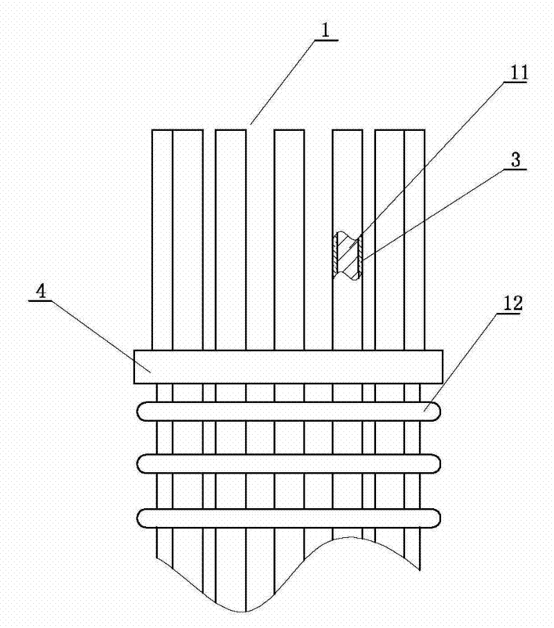
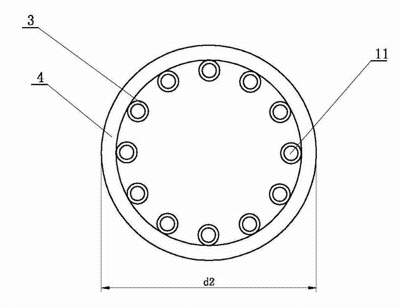
[0034] see Figure 1-7 A method for quick removal of cast-in-place pile pile head concrete, including measuring the cast-in-place pile hole and processing the cast-in-situ pile reinforcement skeleton, the operating steps of the method are:

[0035] A. Process the cast-in-place pile reinforcement skeleton 1 according to the measured cast-in-place pile hole length and diameter; the cast-in-place pile reinforcement skeleton is made up of a pile head and a pile base, and The dividing line is the designed pre-separation position 5, the position above the pre-separation position is the pile head, and the position below the pre-separation position is the pile base; the pile base of the cast-in-place pile reinforcement skeleton includes the lower part of the vertical reinforcement 11 And hoop reinforcement 12, the pile head of described cast-in-situ pile reinforcement skeleton comprises the top of vertical reinforcement 11, the vertical reinforcement of the pile head of described cast...

Embodiment 2

[0047] This embodiment is an improvement made on the basis of Embodiment 1. For the same part as Embodiment 1 in this embodiment, please refer to the content disclosed in Embodiment 1 for understanding, and the content disclosed in Embodiment 1 should also be used as this embodiment. The content of the example will not be repeated here.

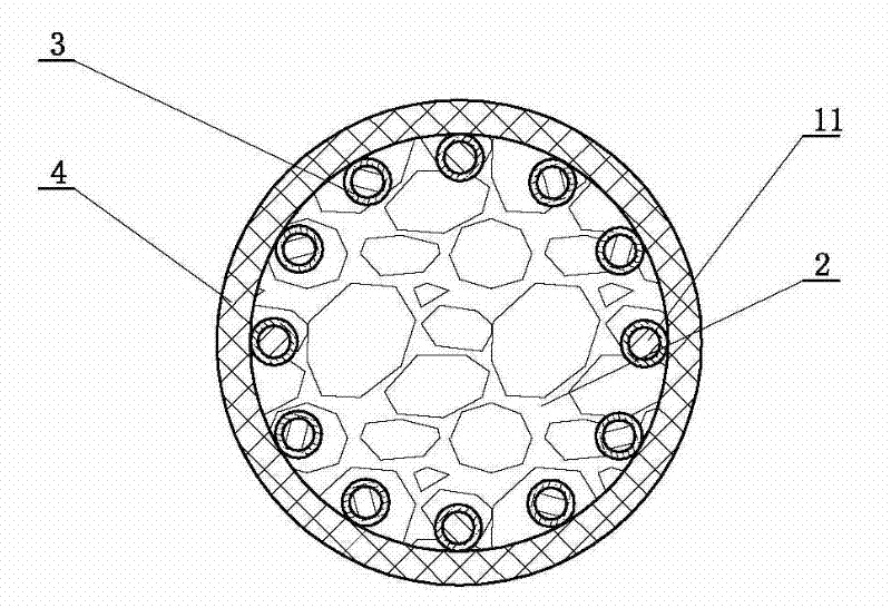
[0048] The upper end of the separation sleeve is flush with the top of the vertical reinforcement at the pile head, and the lower end of the separation sleeve is on the same plane as the lower end of the separation collar. see image 3 , the upper end of the separation sleeve is flush with the top of the vertical steel bar at the pile head, the lower end of the separation sleeve is on the same plane as the lower end of the separation collar, and the lower end of the separation collar is preferably in line with the pre-separation collar. The position is flush. This can better prevent the poured concrete from adhering to the steel skeleton at...

Embodiment 3

[0050] This embodiment is an improvement made on the basis of Embodiment 1. For the same part as Embodiment 1 in this embodiment, please refer to the content disclosed in Embodiment 1 for understanding, and the content disclosed in Embodiment 1 should also be used as this embodiment. The content of the example will not be repeated here.

[0051] see Figure 8 , one end of the separation sleeve is provided with a head.

[0052] The separation sleeve can be used to wrap the vertical steel bar with insulating material, or a sleeve-type separation sleeve can be used. The separation sleeve used in this embodiment is a circular tube-shaped sleeve, and the separation sleeve is directly placed on the vertical steel bar. Preferably, one section of the separation sleeve is provided with a head, and the end with the head is the upper end. , installed on the top of the vertical reinforcement at the head of the pile, and the upper end is closed to prevent concrete from seeping into the...


PUM

PropertyMeasurementUnit
Widthaaaaaaaaaa
Widthaaaaaaaaaa
Wall thicknessaaaaaaaaaa

Abstract

The invention discloses a method for chiseling away cast-in-place pile head concrete rapidly, which comprises the steps of processing a steel bar framework, installing a separating sleeve and a separating sleeve ring on the steel bar framework, placing the steel bar framework into a pouring hole, arranging a template and then pouring concrete and performing maintenance; in chiseling, dismounting the separating sleeve ring to form an annular groove at the bottom of a cast-in-place pile head, using a drilling device to perform drilling construction, and drilling a plurality of pile head separating holes along the annular groove; and using a hoisting device to separate the cast-in-place pile head concrete and a cast-in-place pile foundation after the drilling construction is finished. By means of the method, the cast-in-place pile head concrete can be rapidly chiseled away, time required by pile head concrete chiseling process is shortened, and construction efficiency is improved. Construction operation is simple, special devices and tools and operating workers with professional skill are not required. Construction cost is reduced remarkably, construction quality is high, and accidents due to poor cast-in-place pile head quality are avoided.

Description

technical field [0001] The invention relates to the field of processing after pouring and forming of concrete building components, in particular to a method for quickly chiseling out pile head concrete of cast-in-situ piles. Background technique [0002] Concrete pouring pile is a structural measure often used in industrial and civil construction and foundation construction to improve the bearing capacity of the foundation. It is widely used in high-rise buildings, bridges and some areas with poor ground endurance. Since the concrete on the top layer will be mixed with the mud in the pile hole during the pouring and forming process of the cast-in-place pile, the strength is very low and cannot reach the design strength of the pile body. Therefore, this part of the pile head concrete must be cut off to expose the pile body. vertical steel bars. But for a long time, there has been no good way to deal with the excess concrete at the pile head. It can only be removed manually, ...

Claims


Application Information

Patent Timeline
IPC IPC(8): E02D5/34E02D9/00
Inventor 严少发吴全立刘洋张建锋
Owner CCCC TUNNEL ENG
Why Eureka
Try Eureka