Exhibition cabinet lamp with rotary lamp cap

A lamp head and showcase technology, applied in the field of showcase lights, can solve the problems of large rotating contact surface, inability to ensure long-term effective use of lamp heads, and easy failure.

Active Publication Date: 2014-04-30
SELF ELECTRONICS CO LTD
View PDF2 Cites 0 Cited by
  • Summary
  • Abstract
  • Description
  • Claims
  • Application Information

AI Technical Summary

Problems solved by technology

In this patent, a silicone pad or a corrugated spring is arranged between the bottom surface of the ring and the concave cavity, and the rotating contact surface is relatively large, which is suitable for lamp holders with a spherical surface structure, and the pretightening force generated by this plastic deformation can be used for many times or for a long time. It is easy to fail after time is used, and the effective use of the lamp head cannot be guaranteed for a long time

Method used


Image

  • Exhibition cabinet lamp with rotary lamp cap
  • Exhibition cabinet lamp with rotary lamp cap
  • Exhibition cabinet lamp with rotary lamp cap

Examples


Embodiment Construction

[0020] The present invention will be further described in detail below in conjunction with the accompanying drawings and embodiments.

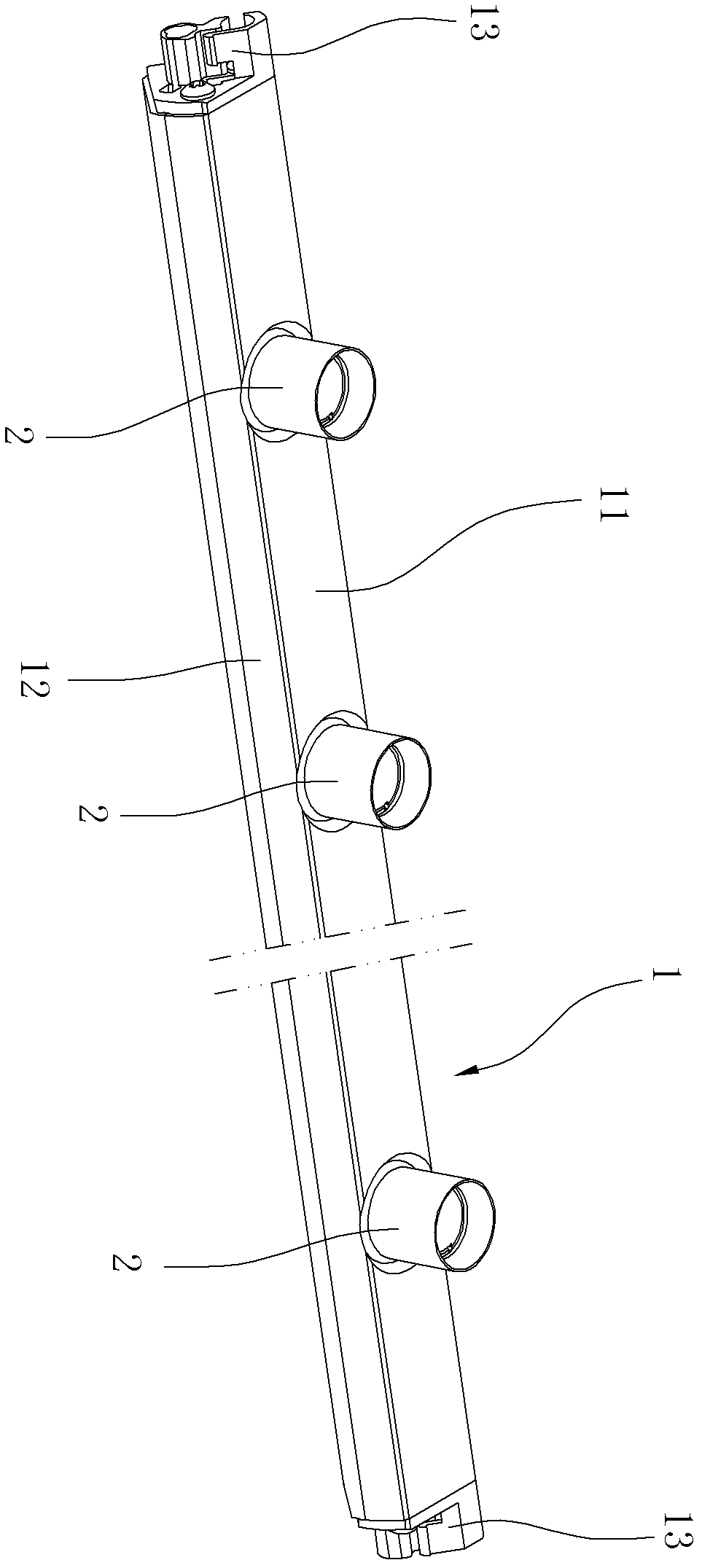
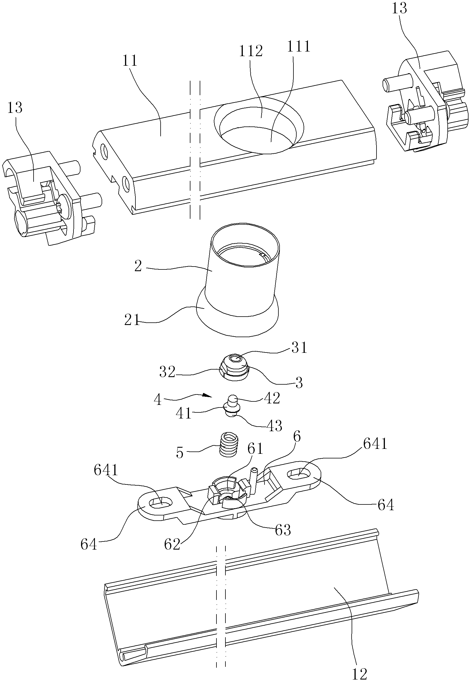
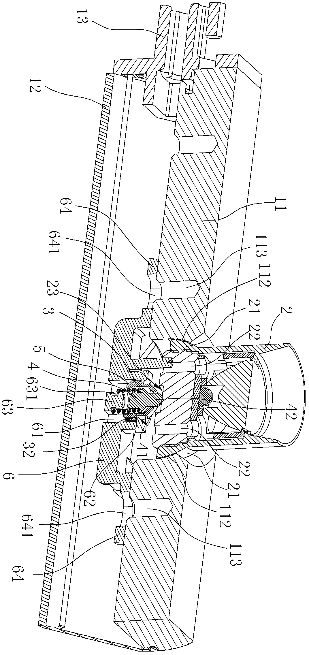
[0021] Such as Figure 1 to Figure 4 As shown, the present embodiment is a display cabinet lamp with LED lighting and a rotatable lamp head. The showcase lamp includes a lamp body 1 and a plurality of lamp holders 2 connected to the lamp body 1. Composed of an upper shell 11 and a lower shell 12 connected together, the lamp body 1 is provided with a plurality of through holes 111 for the lamp holder 2 to pass through in the upper shell 11, and the inner wall of each through hole 111 is formed with a first spherical shape. Surface 112, the cross-section of the first spherical surface 112 is an inverted bowl shape with a small upper end and a larger lower end. The bottom of the outer wall of each lamp cap 2 is formed with a first spherical surface 112 that can cooperate with the through hole 111. Two spherical surfaces 21, the cross-section of ...


PUM


Abstract

The invention discloses an exhibition cabinet lamp with a rotary lamp cap. The lamp comprises a lamp body and a lamp cap which is rotationally connected to the lamp body, and is characterized in that: the bottom of the lamp cap is provided with an elastic driving component; the elastic driving component comprises a spring seat, a positioning pin, a spring and a pressing plate; the positioning pin is accommodated in the spring seat; the spring seat is provided with an end hole through which the head of the positioning pin extends out; the spring is sleeved outside the positioning pin; one end of the spring is axially limited on the positioning pin; a hole cavity is formed on the pressing plate; the spring seat is fixedly arranged in the hole cavity; the other end of the spring is axially limited in the hole cavity; the pressing plate is fixedly connected with the lamp body; and the spring makes the head of the positioning pin always extend out of the spring seat through an end hole and press against the bottom of the lamp cap. By the lamp, elastic pre-tightening force can be generated at the bottom of the lamp cap, the rotating force of the lamp cap can be adjusted by replacing the spring, and the exhibition cabinet lamp has a simple structure and is convenient to mount. Moreover, the lamp cap can be always pressed against the lamp body under the action of the elastic driving component, and the radiating efficiency is improved.

Description

technical field [0001] The invention relates to a lamp, in particular to a showcase lamp with a rotatable lamp head. Background technique [0002] At present, the rotation structure of the lamp head of common lamps is mainly adopted as a limit column at the center of rotation of the lamp head, or by fixing the limit column with a ring to obtain the swing of the lamp head and the rotation of the axis. For example, the Chinese utility model "Adjustable Angle High-Power LED Spotlight" with the patent No. ZL201020633734.0 discloses a high-power LED spotlight with adjustable angle, including a lamp holder; an LED light source assembly and a lampshade; it is characterized in that : The LED spotlight also includes a rotating ring, which is connected and matched with the lampshade and can rotate relative to the lampshade. Two first hinge holes are arranged symmetrically with respect to the axis of the lampholder on the circumference of the lampholder. The axial connection line of t...

Claims


Application Information

Patent Timeline
Patent Type & Authority Patents(China)
IPC IPC(8): F21S8/00F21V21/00F21V29/00F21W131/405F21Y101/02F21V29/502F21Y103/10F21Y115/10
Inventor 徐乐邹伟林万炯
Owner SELF ELECTRONICS CO LTD
Why Eureka
Try Eureka