
Controlled quantity correction circuit used for green new energy automobile cooling cycle system

A new energy vehicle and circuit correction technology, applied in the field of vehicle cooling and heat dissipation, can solve problems such as disturbance, inability to effectively dissipate heat in time, and increase the burden on the controller, and achieve the effect of effective heat dissipation

Active Publication Date: 2019-08-13
ZHENGZHOU INST OF TECH
View PDF4 Cites 7 Cited by
  • Summary
  • Abstract
  • Description
  • Claims
  • Application Information

AI Technical Summary

Problems solved by technology

[0003] However, when an electric vehicle is running, especially the motor and the battery will generate heat at different rates, and the cooling cycle system is when the controller’s sampling is allowed, it will be fed back to the controller according to the heat generated by the battery, and the controller will control the heat dissipation pipeline after analysis and calculation If the heat dissipation is not proportional to the control amount in a control cycle, it will cause the problem of not being able to dissipate heat in a timely and effective manner, and shortening the sampling cycle will cause disturbances and increase the burden on the controller. The output control signal is corrected

Method used


Image

  • Controlled quantity correction circuit used for green new energy automobile cooling cycle system
  • Controlled quantity correction circuit used for green new energy automobile cooling cycle system
  • Controlled quantity correction circuit used for green new energy automobile cooling cycle system

Examples


Embodiment 1

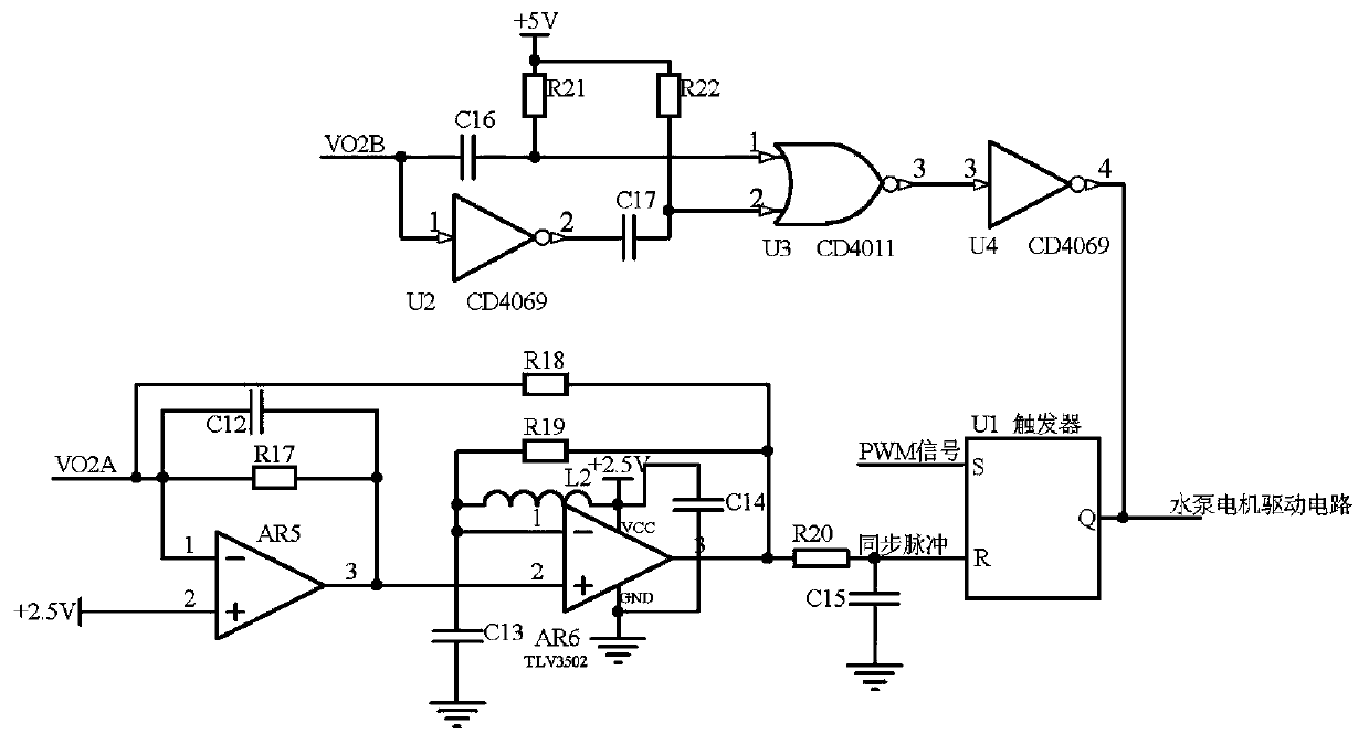
[0015] Embodiment 1, a control quantity correction circuit for a cooling cycle system of a green new energy vehicle, the controller automatically controls the power of the cooling water pump at the corresponding part according to the temperature signal of the outlet water of the engine heat dissipation pipeline of the green new energy vehicle detected by the temperature sensor, Realize the heat dissipation pipeline cooling circulation heat dissipation, the temperature signal detected by the temperature sensor is also connected in sequence with the low-noise amplifier circuit, signal correction circuit, and drive signal compensation circuit to output the compensated drive signal to the cooling water pump according to the temperature change trend, to realize the heat dissipation pipeline The cooling cycle dissipates heat in time;

[0016] The low-noise amplifying circuit receives the voltage signal of the engine temperature of the green new energy vehicle detected by the temperat...

Embodiment 2

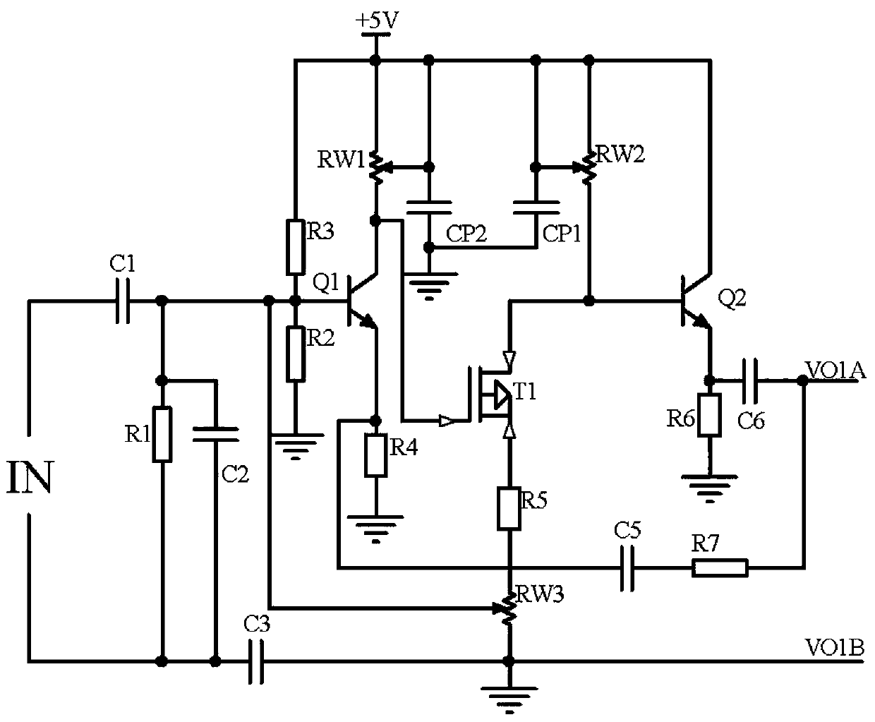
[0017] Embodiment 2, on the basis of Embodiment 1, the low-noise amplifier circuit receives the voltage signal of the engine temperature of the green new energy vehicle detected by the temperature sensor, (a thermistor with a positive temperature coefficient can be used for detection, and the series resistance is 0 -5V for voltage division), the signal output terminal and the ground terminal of the temperature sensor pass through the frequency selection circuit of capacitor C1, capacitor C2, and resistor R1 to filter out other frequency signal interference, and then enter the triode Q1 cascaded field effect transistor T1. The input end of the amplifier performs two-stage low-noise amplification (because the noise of the amplifier itself interferes seriously with the signal when amplifying weak signals, so in order to take into account low-noise generation and high-gain amplification, the triode Q1 and FET T1 are used to input Impedance and output impedance characteristics, casc...

Embodiment 3

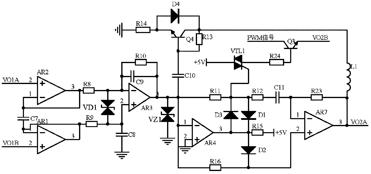
[0018]Embodiment 3, on the basis of Embodiment 2, the signal correction circuit adopts a dual-terminal input / double-terminal output differential amplifier composed of operational amplifiers AR1 and AR2 to receive a low-noise amplified voltage free from common-mode interference and temperature drift After the transient suppression diode VD1 suppresses the electromagnetic interference, the signal enters the inverting input terminal and the non-inverting input terminal of the operational amplifier AR3 respectively, and the differential integrator composed of the operational amplifier AR3, capacitor C8, and capacitor C9 calculates the positive or negative The rate of voltage change, after being regulated by the dual regulator tube VZ1, enters the absolute value circuit composed of operational amplifiers AR4, AR7, diodes D1 and D2, and resistors R11, R12, R15, R16, and R23 to convert it into a positive voltage change rate output. In order to make the output voltage of the absolute v...


PUM


Abstract

The invention discloses a controlled quantity correction circuit used for a green new energy automobile cooling cycle system. A low-noise amplification circuit carries out frequency-selecting filtering on a voltage signal detected by a temperature sensor, the voltage signal is subjected to two-level low noise amplification, the load capacity of the voltage signal is improved by a follower, and then, the voltage signal enters a signal correction signal; the voltage signal is subjected to differential receiving through a differential amplifier; a differential integrator calculates a negative orpositive voltage change rate which is converted into a positive voltage change rate through an absolute value circuit; a bypass circuit is arranged to filter low voltage; a voltage signal of 0.3-+5V is converted into a square wave signal through a PWM (Pulse-Width Modulation) conversion circuit in a driving signal compensation circuit, a pulse signal is synchronized, a signal output to a trigger U1 from a controller is compensated, and a voltage signal which is higher than +5V triggers a high-voltage trigger circuit to be conducted; a controller output signal is directly compensated through atwo-time frequency multiplier in a driving signal compensation circuit to further change a controlled quantity; and therefore, the cooling cycle and the timely and effective heat dissipation of a heatdissipation pipeline can be realized.

Description

technical field [0001] The invention relates to the technical field of automobile cooling and heat dissipation, in particular to a control variable correction circuit for a cooling cycle system of a green new energy automobile. Background technique [0002] Energy shortage, environmental pollution, and climate warming are common challenges faced by the global automobile and energy industries. Governments and industries of various countries have proposed their own development strategies and actively responded to maintain the sustainable development of their automobile and energy industries, and improve the future The international competitiveness of new energy vehicles has become a hot spot in the development of the automotive industry in the future. Electric vehicles can reduce oil consumption and reduce pollutant gas emissions. Temperature stability directly affects the safety and reliability of electric vehicles. A cooling cycle system is usually set up to ensure that the ...

Claims


Application Information

Patent Timeline
Patent Type & Authority Applications(China)
IPC IPC(8): G05D23/32
CPCG05D23/32
Inventor 李晶雷钢叶大萌阎军焦合军
Owner ZHENGZHOU INST OF TECH
Learn More