Electric charge power heat pipe

A power heat pipe and electric charge technology, which is applied in the field of heat pipes, can solve problems such as the inability of components to dissipate heat and the obstruction of liquid return, and achieve the effect of effective heat dissipation circulation and high efficiency

Inactive Publication Date: 2016-04-13
HEFEI LCFC INFORMATION TECH
View PDF8 Cites 0 Cited by
  • Summary
  • Abstract
  • Description
  • Claims
  • Application Information

AI Technical Summary

Problems solved by technology

Traditional water conduits are limited by space, and in the narrow convective space, the return flow of liquid is hindered, which causes the components to continuously accumulate heat and fail to dissipate heat

Method used


Image

  • Electric charge power heat pipe
  • Electric charge power heat pipe
  • Electric charge power heat pipe

Examples


Embodiment approach 1

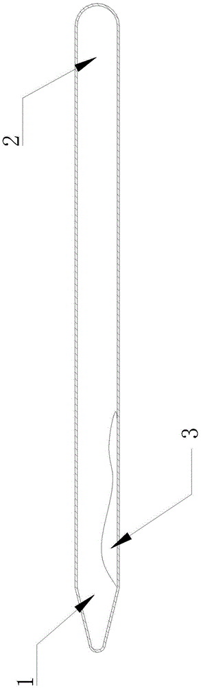
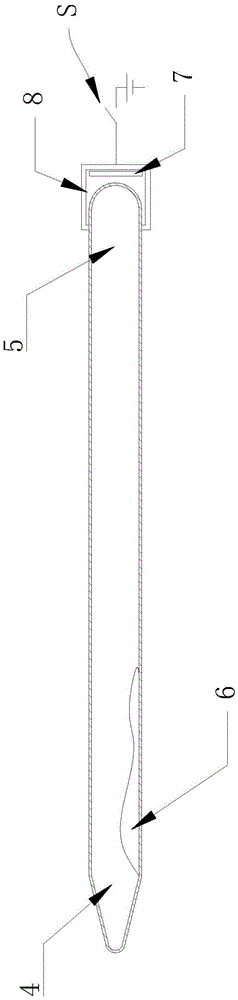
[0019] Such as figure 2 As shown, the electric charge dynamic heat pipe of the present invention has a vacuum tube body, and the vacuum tube body has a cooling section 4 and a heating section 5, and the radius of the cooling section 4 tapers into a conical shape. A certain amount of negative ion water 6 is also filled in the vacuum tube body, and the negative ion water evaporates when heated in the heating section 5, and flows back to the cooling section 4, then cools and recondenses into a liquid, and then flows back to the heating section 5, so that the heat dissipation function is realized by circulation.

[0020] A ceramic sleeve 8 is arranged at the end of the heating section 5 for insulation, and an anode plate 7 is arranged between the ceramic sleeve 8 and the end of the heating section 5 to drain the negative ion water 6 . In addition, an auxiliary circuit is provided. The positive electrode of the power supply is connected to the anode plate 7 through the switch S. W...

Embodiment approach 2

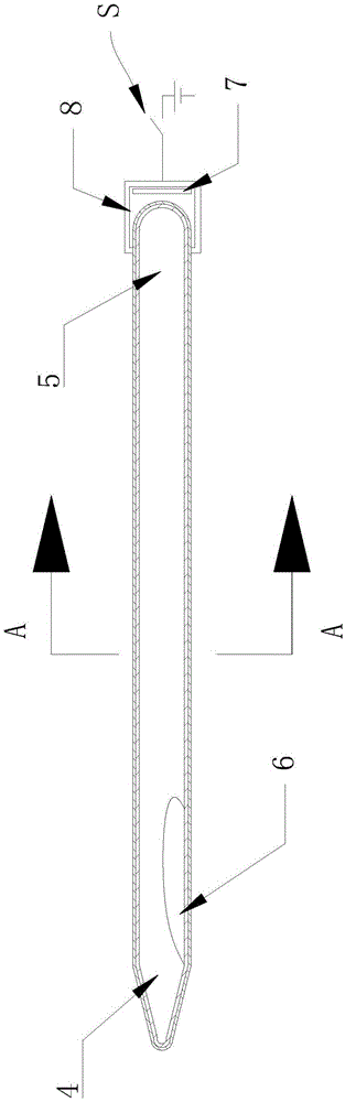
[0023] The structure of the charge dynamic heat pipe of the present embodiment is as follows: Figure 3-4 shown. The vacuum tube body has a cooling section 4 and a heating section 5. The tube body is filled with negative ion water 6. The end of the heating section 5 is provided with a ceramic sleeve 8 and an anode plate 7. It also has an auxiliary circuit connected to the anode plate 7. The above structure is the same as that of Embodiment 1, and will not be repeated here. Such as Figure 4 As shown in the cross-sectional view of the tube body, a capillary return layer 10 is provided on the lumen wall 9 of the tube body. The capillary reflow structure 10 can be sintered copper powder and other prior art to form a capillary structure, such as braided mesh layer, sintered copper powder layer or sintered fiber layer.

[0024] For the working principle of this embodiment. The negative ion water 6 is absorbed by the anode plate 7 and evaporates into water vapor in the heating s...


PUM


Abstract

The invention discloses an electric charge power heat pipe. The electric charge power heat pipe comprises a pipe body; the pipe body is a vacuum pipe; the pipe body has a cooling section and a heated section; an insulation pipe sleeve is arranged at the end part of the heated section; an anode plate is arranged between the end part of the heated section and the insulation pipe sleeve; and in addition, negative ion liquid is filled in the pipe body. Under dual effects of air pressure difference and capillary structure, cooling steam can quickly flow to the cooling section, and cooled cooling liquid can quickly flow back to the heated section under the effects of the anode plate and an auxiliary circuit, so that the cooling circulation can be performed more effectively, and the efficiency is higher.

Description

technical field [0001] The invention relates to a heat pipe of a radiator, in particular to a charge power heat pipe. Background technique [0002] At present, in the heat sink of electronic equipment, the heat pipe becomes the most important part of the heat sink. Most of the heat pipes used in the prior art are as figure 1 The copper water heat pipe has a condensation section 1 and an evaporation section 2. The heat pipe is an integrated structure with a smooth transition connection, and copper water 3 is injected in the middle. The copper water 3 evaporates in the condensation section after absorbing heat in the heating section 1. 2 Condensate and flow back to the heating section 1, and this circulation process realizes heat dissipation. However, as the market demands more and more light and thin electronic products, heat conductors are also becoming thinner and thinner. Traditional water conduits are limited by space. In the narrow convective space, the return flow of...

Claims


Application Information

Patent Timeline
IPC IPC(8): F28D15/04
CPCF28D15/043
Inventor 徐阿祥叶振兴
Owner HEFEI LCFC INFORMATION TECH
Why Eureka
Try Eureka