Cooling fin point welding machine of transformer finned radiator

A technology of heat sinks and radiators, applied in welding equipment, resistance welding equipment, metal processing equipment, etc., can solve problems such as difficulty in planning spot welding machines, save labor resources, improve spot welding efficiency, and reduce occupied space. Effect

Inactive Publication Date: 2012-07-04
CHANGSHU YOUBANG RADIATOR
View PDF15 Cites 13 Cited by
  • Summary
  • Abstract
  • Description
  • Claims
  • Application Information

AI Technical Summary

Problems solved by technology

The current solution is to increase the number of spot welders to meet the production requirements of radiators. However, this measure is originally a negative measure, because it not only increases the investment in equipment, occupies valuable production space, but also increases the number of labor forces. , especially the spot welding position is uneven, that is, whether it is in the horizontal or vertical direction, it is difficult to align the position of the welding spot, which not only affects the viewing effect, but also makes it difficult to guarantee the quality of spot welding
[0005] Even in the "welding machine for radiator fins" recommended by Chinese patent utility model authorization announcement number CN201950359U and "a special welding machine for radiators" provided by CN201493618U It is also difficult to plan a spot welding machine that can make up for the aforementioned shortcomings under the inspiration of the technical content of the

Method used


Image

  • Cooling fin point welding machine of transformer finned radiator
  • Cooling fin point welding machine of transformer finned radiator
  • Cooling fin point welding machine of transformer finned radiator

Examples


Embodiment Construction

[0022] In order to enable the examiners of the patent office, especially the public, to understand the technical essence and beneficial effects of the present invention more clearly, the applicant will describe in detail the following in the form of examples, but none of the descriptions to the examples is an explanation of the solutions of the present invention. Any equivalent transformation made according to the concept of the present invention which is merely formal but not substantive shall be regarded as the scope of the technical solution of the present invention.

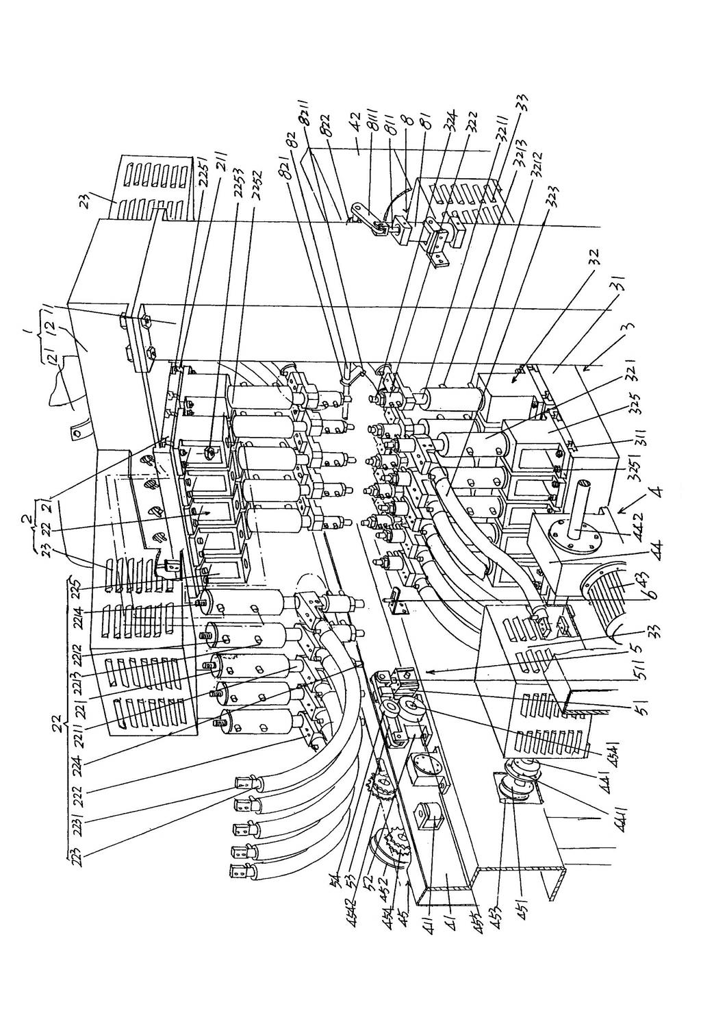
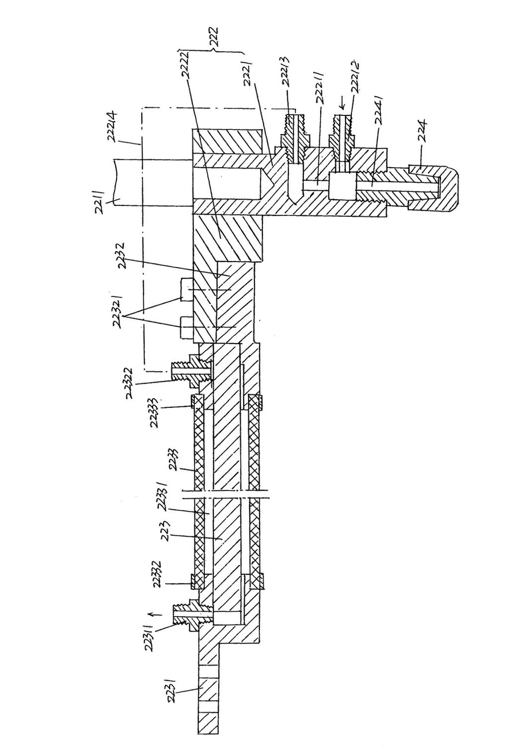
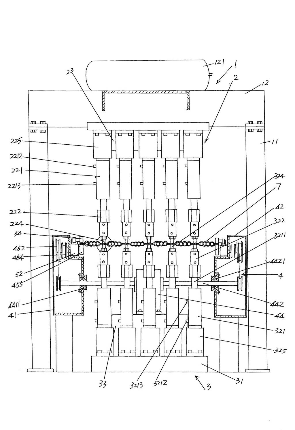
[0023] See figure 1 , a frame 1 is given, the frame 1 is composed of a pair of columns 11 and a beam 12 parallel to each other longitudinally, and the bottom ends of a pair of columns 11 are fixed on the ground in the state of use, that is, fixed at the place of use On the floor, one end of the beam 12 is fixedly connected to the top of one of the columns 11 in the pair of columns 11, and the other end o...


PUM


Abstract

The invention relates to a cooling fin point welding machine of a transformer finned radiator, and belongs to the technical field of welding machines. The cooling fin point welding machine comprises a rack, upper and lower point welding mechanisms, and a cooling fin convey mechanism, wherein the rack is composed of a pair of upright posts and a beam, and an air tank is arranged on the beam; the upper point welding mechanism comprises a first base and at least two groups of upper point welding devices and upper electric welders, and the lower point welding mechanism comprises a second base, lower point welding devices and lower electric welders the quantity of which are equal to that of the upper point welding devices; the lower point welding devices are electrically connected with the lower electric welders, and also are connected with a gas path of the air tank; and the second base is arranged on the bottom corresponding to the space between the pair of upright posts, and is corresponding to the first base. The cooling fin point welding machine provided by the invention has the advantages of being capable of remarkably improving point welding efficiency on cooling fins on the premise of not increasing the quantity of single point welding machines, being capable of saving equipment investment, reducing occupancy space of a production field and saving labor resources, and particularly being capable of insuring finishing effects of bonding points and guaranteeing the welding quality of the cooling fins.

Description

technical field [0001] The invention belongs to the technical field of welding machines, and in particular relates to a heat sink spot welding machine for a transformer fin radiator. Background technique [0002] As known in the industry, in order to make the transformer (oil-immersed transformer) operate normally, it is usually necessary to install a radiator on the side and / or upper part of the transformer, and the radiator will play the role of reducing the temperature rise of the transformer. Get a full understanding of the patented technical solutions that are not limited to those listed below and disclosed by Chinese patent documents. Such as CN201084519Y (transformer radiator), CN101339838A (radiator ladder radiator), CN201185118Y (transformer radiator), CN201185115Y (radiator with fan base), CN201185117Y (transformer radiator), CN201256051Y and CN101388275A (transformer heat exchanger using evaporative cooling technology), etc. [0003] Furthermore, as known in the...

Claims


Application Information

Patent Timeline
Patent Type & Authority Applications(China)
IPC IPC(8): B23K11/11B23K11/36
Inventor 王建忠严江
Owner CHANGSHU YOUBANG RADIATOR
Why Eureka
Try Eureka