Linkage clamp

A technology of fixture and linkage mechanism, applied in the direction of clamps, manufacturing tools, auxiliary devices, etc., can solve the problem of inability to make changes, and achieve the effect of large opening angle, preventing vibration and splashing

Inactive Publication Date: 2012-07-04
DELAWARE CAPITAL FORMATION INC
View PDF5 Cites 4 Cited by
  • Summary
  • Abstract
  • Description
  • Claims
  • Application Information

AI Technical Summary

Problems solved by technology

Although fixtures work well for their intended purpose, they cannot be altered to be used for a different type of operation

Method used


Image

  • Linkage clamp
  • Linkage clamp
  • Linkage clamp

Examples


Embodiment Construction

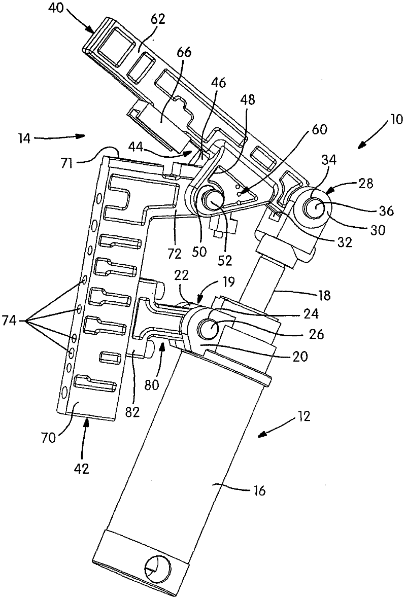
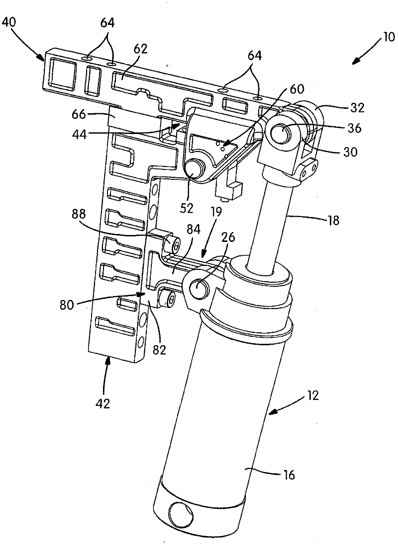
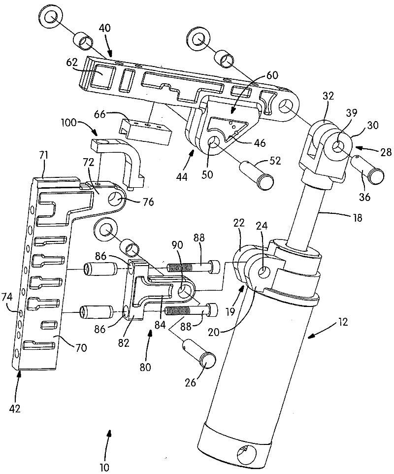
[0016] Referring to the drawings, a clamp assembly is illustrated and designated by the reference numeral 10 . The clamp assembly 10 includes an actuator 12 and a linkage 14 . Actuator 12 may be a pneumatic or hydraulic cylinder as shown. Furthermore, an electric linear drive can be used as the actuator 12 .

[0017] The actuator 12 includes a housing 16 having a rod 18 extending from the housing 16 . While not shown, rod 18 is connected to a piston that moves in response to fluid pressure within housing 16 as is known to those skilled in the art. A clevis 19 protrudes from the housing 16 . The clevis 19 includes a pair of ears 20 , 22 each having an aperture 24 for receiving a clevis pin 26 . Piston rod 18 also includes a clevis 28 having a pair of ears 30 , 32 including a bore 34 for receiving a clevis pin 36 .

[0018] The linkage mechanism 14 includes a link member 40 and a base member 42 . Linkage member 40 includes a clevis 44 having ears 46 , 48 . The ears includ...


PUM


Abstract

A clamp has a powered actuator that includes an arm moving between a first and a second position. A linkage mechanism has a link and a base. The link and base are pivotally connected with one another. The link couples with the arm of the cylinder. The bracket couples with the actuator and the base. The bracket is movable along the base for adjusting the angle opening between the link and the base.

Description

[0001] Cross References to Related Applications [0002] This application claims the benefit of US Provisional Application No. 61 / 410,487, filed November 5, 2010. The entire disclosure of the above application is hereby incorporated by reference. technical field [0003] The present disclosure relates to a clamp, and more particularly, to an open power clamp. Background technique [0004] Previous power clamps have included housings enclosing the clamping structure. Therefore, the gripper can be used to operate alone. Although fixtures work well for their intended purpose, they cannot be altered to be used for a different type of operation. Contents of the invention [0005] The present disclosure provides a clamp having an adjustable splay angle that enables the clamp to be used in a variety of operations. The air cylinder can be located on the base of the linkage and can be mounted at various positions along the base to provide different splay angles. The present di...

Claims


Application Information

Patent Timeline
Patent Type & Authority Applications(China)
IPC IPC(8): B23K37/04
CPCB25B5/064B25B5/006B25B5/16B25B5/06B23K37/0435
Inventor 彼得・绍斯
Owner DELAWARE CAPITAL FORMATION INC
Why Eureka
Try Eureka