
Liquid ejection apparatus and drive circuit thereof

A driving circuit and driving voltage technology, applied in printing and other directions, can solve problems such as leakage and inability to completely eliminate pinholes

Active Publication Date: 2012-07-04
TOSHIBA TEC KK
View PDF6 Cites 9 Cited by
  • Summary
  • Abstract
  • Description
  • Claims
  • Application Information

AI Technical Summary

Problems solved by technology

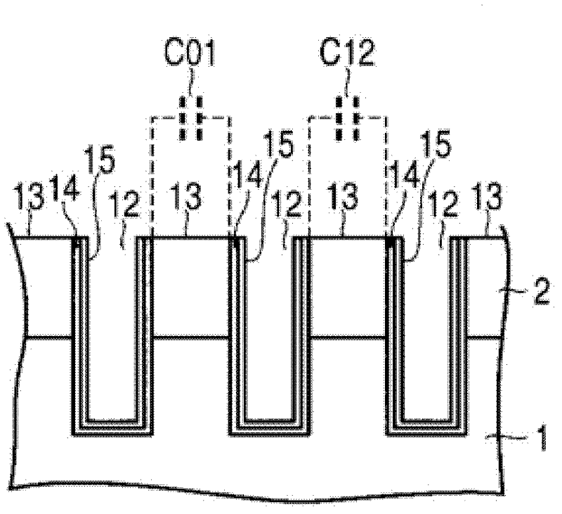
[0008] Even if an insulating film is formed, pinholes (pin holes) generated in the insulating film cannot be completely eliminated
Current leaks from the electrode to the ink side through the pinhole, resulting in electrolysis as described above
Even if it is a slight current leakage in the initial stage, it will become a problem that cannot be ignored if it continues for a long time

Method used


Image

  • Liquid ejection apparatus and drive circuit thereof
  • Liquid ejection apparatus and drive circuit thereof
  • Liquid ejection apparatus and drive circuit thereof

Examples


no. 1 approach

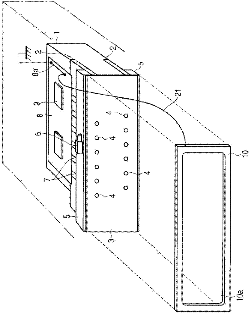
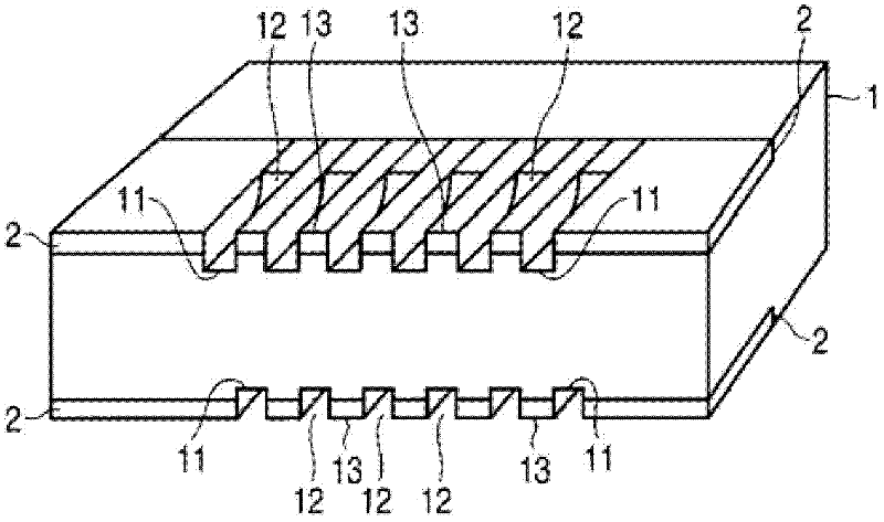
[0035] Hereinafter, a first embodiment of the present invention will be described with reference to the drawings. figure 1 The overall structure of the inkjet head, which is the liquid ejection device, is shown, figure 2 A state in which the nozzle plate of the inkjet head is removed is shown.

[0036] A plate-shaped piezoelectric member 2 is embedded in a region along one side edge of the upper surface of the base 1 formed of the piezoelectric member. The end surface of the piezoelectric member 2 is formed flush with the side surface of the base 1 . A plate-shaped piezoelectric member 2 is also embedded in a region along one side edge of the lower surface of the base 1 . The end surface of the piezoelectric member 2 is formed flush with the side surface of the base 1 .

[0037] A nozzle plate (also referred to as an orifice plate) 3 formed of an insulating member is disposed on the end surface of the piezoelectric member 2 and the side surface of the base 1 . The nozzle ...


PUM


Abstract

Provided are a liquid ejection apparatus and a drive circuit thereof, which can drive an actuator quickly enough and can eliminate problems of producing foreign substances in the ink in the pressure chambers and of dissolving or corroding the electrodes and prevent the ink from changing in quality. A direct current voltage which has positive and negative potentials relative to a ground potential interposed therebetween is used as a drive voltage for electric charging / discharging to / from an actuator.

Description

technical field [0001] Embodiments of the present invention relate to a liquid ejection device and a drive circuit thereof used in an inkjet printer or the like. Background technique [0002] The so-called inkjet head, which is a liquid ejection device used in an inkjet type printer, consists of a plurality of pressure chambers that guide liquid, that is, ink, and a plurality of static electricity that applies pressure for ink introduction and ink ejection to these pressure chambers. Capacitive loads such as piezoelectric elements, a plurality of electrodes for applying drive voltage to these piezoelectric elements, and nozzle plates (also called orifice plates) each having ink ejection nozzles at positions corresponding to the above-mentioned pressure chambers , a mask plate for protecting the nozzle plate, and the like. Capacitive actuators are formed by piezoelectric elements and electrodes, respectively. The cover plate is grounded in order to discharge static electric...

Claims


Application Information

Patent Timeline
IPC IPC(8): B41J2/045
CPCB41J2/04573B41J2/04541B41J2/04581B41J2/0455B41J2/04548
Inventor 日吉光幸仁田昇木村守吉丸朝久
Owner TOSHIBA TEC KK
Learn More