Automatic connecting/disconnecting device for braking air ducts of railroad vehicles

A technology for railway vehicles and disconnectors, applied in railway couplings, railway car body parts, transportation and packaging, etc., can solve the problems of low degree of automation, low efficiency, threats to the personal safety of operators, etc., and achieve a high degree of automation. , The effect of easy maintenance and shortening of operation speed

Inactive Publication Date: 2014-06-11
白鹏
View PDF6 Cites 0 Cited by
  • Summary
  • Abstract
  • Description
  • Claims
  • Application Information

AI Technical Summary

Problems solved by technology

[0003] This method of operation requires the operator to enter between the two compartments to manually complete the joining and separation of the air pipe joints between the adjacent two compartments, and the connection and closure of the ventilation plug door. This kind of operation method is completely manual operation, and the degree of automation is low. , low efficiency, and poses a certain threat to the personal safety of operators

Method used


Image

  • Automatic connecting/disconnecting device for braking air ducts of railroad vehicles
  • Automatic connecting/disconnecting device for braking air ducts of railroad vehicles
  • Automatic connecting/disconnecting device for braking air ducts of railroad vehicles

Examples


Embodiment 1

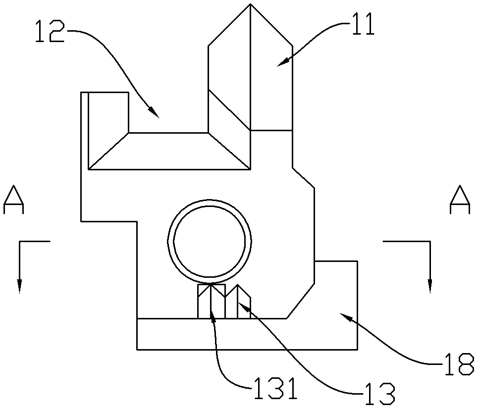
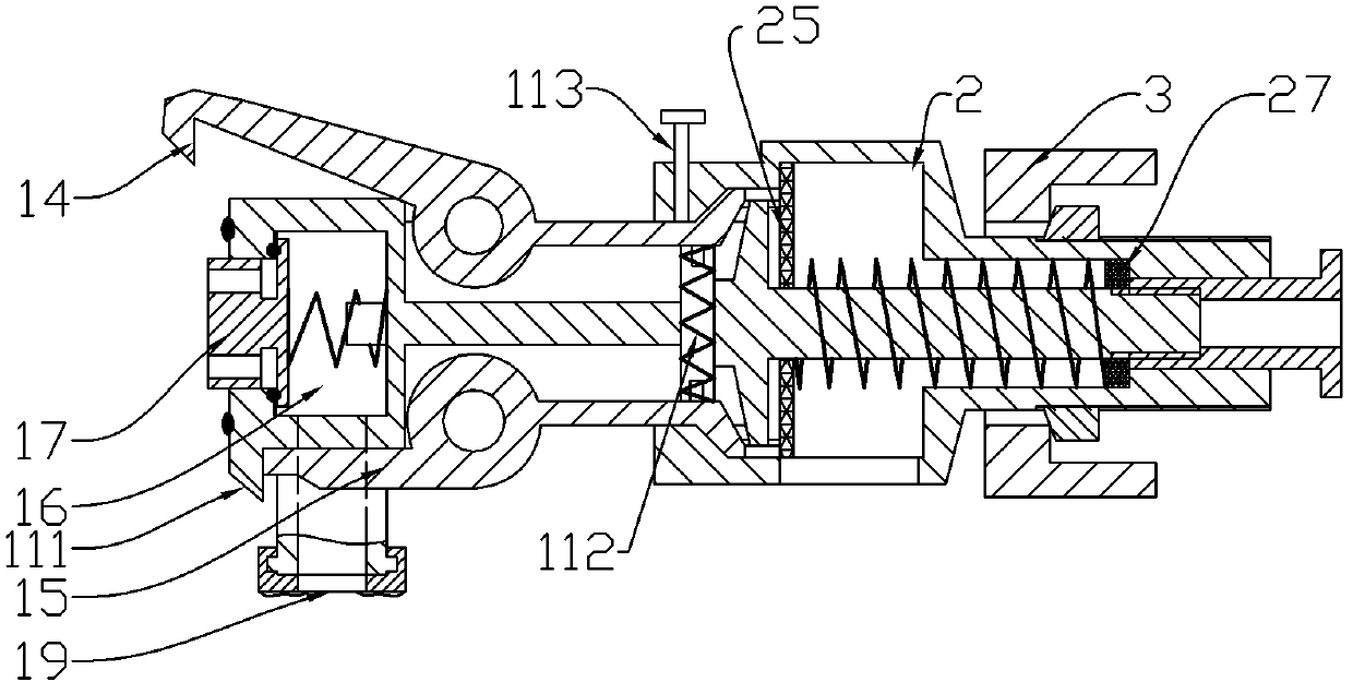
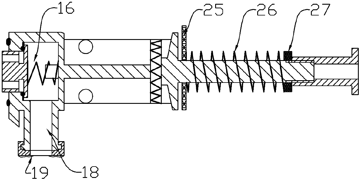
[0028] Such as Figure 1~6 As shown, this automatic brake air pipe coupler for railway vehicles includes a coupler main body 1 , a box cover 2 and a mounting seat 3 for fixing.

[0029] The cross-section of the front half of the main body 1 of the joint is square, and the cross-section of the second half is circular; There are positioning protrusions 13 and positioning grooves 131, and the two sides and the upper and lower sides of the adjustment protrusions are all curved surfaces. After the main bodies of the two connectors adjacent to each other are close to each other, under the action of external force, the two connectors are firstly adjusted through the left and right adjustment protrusions, and then the precise positioning is realized through the positioning protrusions. They are gradually closed in the way of insertion, and they together form an adjustment mechanism, which is a guided insertion structure.

[0030] On both sides of the front part of the receiver main ...

Embodiment 2

[0042] Such as Figure 10 ~ Figure 12 as shown,

[0043] The difference from Embodiment 1 lies in the difference in the valve assembly. In this embodiment, the valve assembly is an angle valve, also called a rotary valve, which controls the opening and closing of the valve through the rotation of the valve core. This knuckle valve has a similar structure to the existing knuckle plug. The knuckle valve includes a spherical or columnar valve core 41 installed in the cavity. In this state, similar to the structure of the existing ball valve, the valve core 41 is integrated with a valve handle through a rotating shaft. In order to cooperate with the function of automatic connection, the key point is to improve the shape of the valve handle 42. The valve handle 42 is semi-circular and located on the lower side of the valve core, and is provided with and opposite to the valve on the front surface of the main body of the connector. The push-pull rod matched with the handle, the end...


PUM


Abstract

The invention discloses an automatic connecting / disconnecting device for braking air ducts of railroad vehicles, which belongs to an accessory device for railways. The device comprises a connecting / disconnecting device main body, a case and an installing seat, wherein the front end face of the device is provided with an aligning bulge and an aligning groove, and the lower half part of the front end face is provided with a positioning bulge or a positioning groove, thereby forming an aligning structure; the two sides of the front part of the connecting / disconnecting device main body are respectively oppositely provided with a lock hook and an unlocking bar so as to form an automatic locking / unlocking structure; the rear part of the connecting / disconnecting device main body can be slidably nested in the case; the inside of the case is provided with a buffer structure; the rear part of the case is nested in a hole of the installing seat; and the installing seat is fixed right above or below a car coupler. By using the device disclosed by the invention, six seventh of connecting / disconnecting workload in the process of carrying out marshalling on railroad vehicles is reduced, the running speed of railway logistics is greatly reduced, and an operation of connecting and disconnecting air ducts between carriages of a vehicle is performed without operators, thereby ensuring the personal safety of operators.

Description

technical field [0001] The invention relates to a connecting device for a railway vehicle brake air duct, which is used for the connection and separation of the railway vehicle air duct and the connection and closure of ventilation, in particular to an automatic connector for the railway vehicle brake air duct. Background technique [0002] Since the railway vehicle brake adopts the pneumatic method, the air duct of the vehicle is manually operated, and the operation process is as follows: ① The operator enters between the two carriages and manually connects the connector; ② Open the angled plug at one end of the air duct Door; ③Open the corner cock door at the other end; Solution: ①The operator enters between the two compartments before the coupler is separated, and closes the corner cock door at the wind-incoming end; ②Closes the other corner cock door; ③Opens the connector manually. [0003] This method of operation requires the operator to enter between the two compartme...

Claims


Application Information

Patent Timeline
Patent Type & Authority Patents(China)
IPC IPC(8): B61G5/08
Inventor 白鹏
Owner 白鹏
Why Eureka
Try Eureka