
Conveying chain

A technology of conveying chain and inner chain plate, applied in the field of conveying chain, can solve the problems of increasing material cost, polluting the environment, short lubrication time, etc., and achieve the effect of improving service life

Inactive Publication Date: 2012-07-04
SUZHOU UNIVERSAL GRP TECH CO LTD
View PDF0 Cites 3 Cited by
  • Summary
  • Abstract
  • Description
  • Claims
  • Application Information

AI Technical Summary

Problems solved by technology

However, the traditional conveyor chain needs to be refueled and maintained frequently. Even the so-called self-lubricating chain, as the use time increases, the lubrication effect is no longer obvious, and the service life of the chain cannot be guaranteed at all.
Moreover, the traditional conveyor chain is often refueled and maintained, and the lubrication time after one refueling is very short. If drip oil lubrication is used, it will not only increase the cost of materials, but also pollute the environment and increase additional environmental maintenance costs.

Method used


Image

  • Conveying chain
  • Conveying chain
  • Conveying chain

Examples


Embodiment Construction

[0022] The present invention will be described below with reference to the drawings.

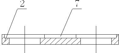
[0023] As attached Figure 1-9 The conveyor chain of the present invention shown includes a first inner link plate 1, a second inner link plate 2, an outer link plate 3, a pin 4, a roller 5, and a sleeve 6. The roller 5 A first inner link plate 1 and a second inner link plate 2 are provided at both ends, and the outer ends of the first inner link plate 1 and the second inner link plate 2 are each provided with an outer link plate 3, the pin 4 Connect the roller 5, the first inner link plate 1, the second inner link plate 2 and the two outer link plates 3 together, and the pin 4 is connected to the first inner link plate 1, the second inner link plate 2 and A sleeve 6 is provided between the rollers 5, and the thickness of the second inner link plate 2 is greater than the thickness of the first inner link plate 1; a communicating oil storage groove 7 is provided between the two holes of the sec...


PUM


Abstract

The invention discloses a conveying chain. The conveying chain comprises a first inner chain plate, a second inner chain plate, outer chain plates, a pin shaft, a roller and a sleeve. The first inner chain plate and the second inner chain plate are arranged at the two ends of the roller. One outer chain plate is arranged at each of the outer ends of the first inner chain plate and the second inner chain plate respectively. The roller, the first inner chain plate, the second inner chain plate and the two outer chain plates are connected together by the pin shaft. The sleeve is arranged between the pin shaft and the first inner chain plate, and between the second inner chain plate and the roller. The second inner chain plate is thicker than the first inner chain plate. Communicated oil storing slots are arranged between the two holes of the second inner chain plate. A cover plate is fixed on the second inner chain plate by a fixing pin. An oil filling slot is arranged on one surface of the cover plate. One end of the sleeve, close to the second inner chain plate, is provided with a notch. A slot forming an included angle with the axial direction of the sleeve is arranged at the position on the sleeve, corresponding to the notch. A large chamfering is arranged at one end of the second inner chain plate, where the inner diameter of the roller closes to. According to the conveying chain disclosed by the invention, long-time lubrication is realized after oil filling in one time, and the sleeve, the roller and the pin shaft are ensured to be fully lubricated.

Description

Technical field [0001] The invention relates to a conveying chain, in particular to a conveying chain that can not only achieve the purpose of long-term lubrication at one time, but also ensure the full lubrication of sleeves, rollers and pins, belonging to the technical field of transmission chains. Background technique [0002] At present, with the continuous development of automated production, conveyor chains have been widely used in assembly lines, production equipment and other fields. This is because chain conveyors have the advantages of horizontal, inclined, vertical or mutual combination, and can adapt to Various packaging forms of material transportation can meet different production needs. However, the traditional conveyor chain requires frequent refueling and maintenance. Even the self-lubricating chain, as it is often said, has long been insignificant with the use of time, and the service life of the chain is not guaranteed. Moreover, the traditional conveyor chain...

Claims


Application Information

Patent Timeline
Patent Type & Authority Applications(China)
IPC IPC(8): B65G17/40
Inventor 黄伟达
Owner SUZHOU UNIVERSAL GRP TECH CO LTD
Learn More