
High-speed cap separating mechanism

A high-speed, cover-separating technology, which is applied in the direction of object destacking, transportation and packaging, can solve the problems of low efficiency and high labor intensity, and achieve the effect of low cost, easy realization and high efficiency of cover separation

Inactive Publication Date: 2012-07-04
CENT SOUTH UNIV
View PDF8 Cites 31 Cited by
  • Summary
  • Abstract
  • Description
  • Claims
  • Application Information

AI Technical Summary

Problems solved by technology

For this kind of can lids, only manual separation can be used at present, which is low in efficiency and labor-intensive, and has become the bottleneck of can sealing automation.

Method used


Image

  • High-speed cap separating mechanism
  • High-speed cap separating mechanism
  • High-speed cap separating mechanism

Examples


Embodiment Construction

[0021] The present invention will be further described in detail below in conjunction with the embodiments and the accompanying drawings, but the embodiments of the present invention are not limited thereto.

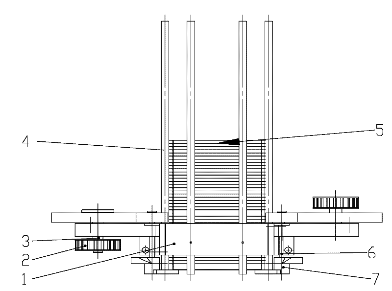
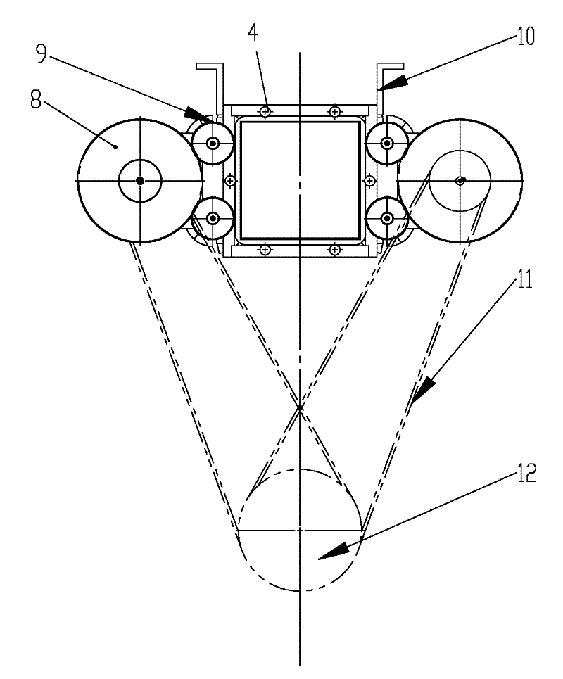
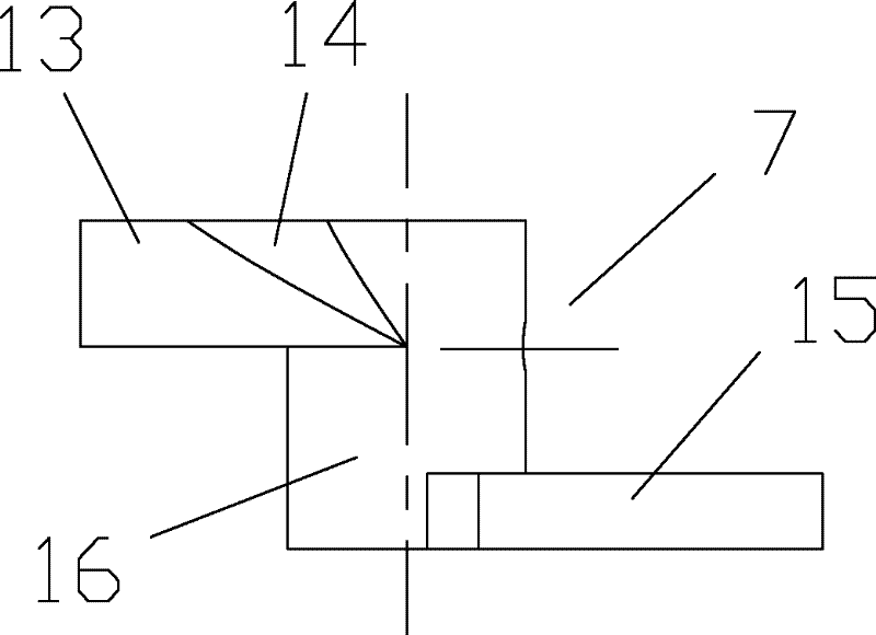
[0022] see figure 1 , figure 2 , image 3 , Figure 4 and Figure 5 , the sub-cover seat 1 is installed on the mounting bracket 10, and the 6 cover bin guide rods 4 are vertically installed in the holes of the sub-cover seat 1 whose shape is adapted to the shape of the sealed can lid. touch. There are 4 sub-cover parts installed on the bottom of the cover bin. The sub-cover part is a double-layer dial, which is composed of an upper wheel 13 and a lower wheel 15 connected by a central bushing 16. The projection of the lower wheel 15 is a sector with a central angle of less than 180 degrees. , the upper surface is a plane, the projection of the upper wheel 13 is fan-shaped, and the central angle is 180 ± 10 degrees. The upper and lower fan-shaped symmetry lines of 1...


PUM


Abstract

The invention discloses a high-speed cap separating mechanism, which comprises a cap bin, transmission components and cap separating components, wherein the cap bin is placed vertically; at least 2 cap separating components are arranged at the bottom of the cap bin; each cap separating component consists of double layers of shifting wheels and is formed by connecting an upper wheel (13) and a lower wheel (15) through a central shaft sleeve (16), the projection of the lower wheel (15) is in a shape of sector of which central angle is less than 180 degrees, the upper surface of the lower wheel (15) is a plane, the projection of the upper wheel (13) is in a shape of sector of which central angle is 180+ / -10 degrees, the lower surface of the upper wheel (13) is a plane, the edge of the upper surface of the upper wheel (13) is provided with a spiral face (14), the directions of the symmetric lines of the sectors of the upper wheel (13) and the lower wheel (15) are opposite, and the distance between the lower surface of the upper wheel (13) and the upper surface of the lower wheel (15) is the thickness of a tank cap; and the central shaft sleeve (16) of each cap separating component is in transmission connection with the transmission component. The high-speed cap separating mechanism enables the easily nested tank cap to be automatically separated at a high speed, and has high cap separating efficiency.

Description

technical field [0001] The invention relates to a high-speed lid separating mechanism that can be used for an automatic can seaming machine, in particular to a mechanism that can realize high-speed automatic separation of special-shaped and easy-to-nest can lids. Background technique [0002] Separating stacks of can lids one by one is a necessary process for automatic can sealing. Existing automatic can seamer high-speed lid separation technologies such as Chinese patents CN2714196Y, CN102060253A, CN201261708Y, etc. are all aimed at round and difficult to nest lids. Due to the continuous improvement of people's requirements for product packaging, there have been many can lids with irregular shapes such as squares and polygons that are prone to nesting. For this type of can lids, only manual separation can be used at present, which is inefficient and labor-intensive, and has become the bottleneck of can sealing automation. Contents of the invention [0003] The technical...

Claims


Application Information

Patent Timeline
IPC IPC(8): B65G59/06
Inventor 韩奉林严宏志
Owner CENT SOUTH UNIV
Learn More