
Lifting appliance

A spreader and hook technology, which is applied in the field of spreaders, can solve the problems of low operating efficiency, high risk factor, high labor intensity, etc., and achieve the effects of convenient operation, low cost, and reduced safety hazards

Active Publication Date: 2012-07-04
HONGHUA OIL & GAS ENG SERVICE SICHUAN
View PDF8 Cites 3 Cited by
  • Summary
  • Abstract
  • Description
  • Claims
  • Application Information

AI Technical Summary

Problems solved by technology

[0004] But it has the following deficiencies: when realizing the hook and taking the hook, that is, when the rope is hung from the outside of the hook or the rope is taken out of the inside of the hook, it is necessary to manually assist the blocking device to be pressed away from the hook to form a rope for use. The rope can only be detached from the hook after there is a moving space. Usually, the operator needs to climb to the vicinity of the hook for manual operation, which takes a long time and has low safety
[0005] Especially for the hooks that work at heights above 10m from the ground, if the operator needs to climb to the vicinity of the hook for manual operation every time the hook is hooked and removed, not only the risk factor is high, but also the labor intensity is high and the operation efficiency is low.

Method used


Image

  • Lifting appliance
  • Lifting appliance
  • Lifting appliance

Examples


Embodiment 1

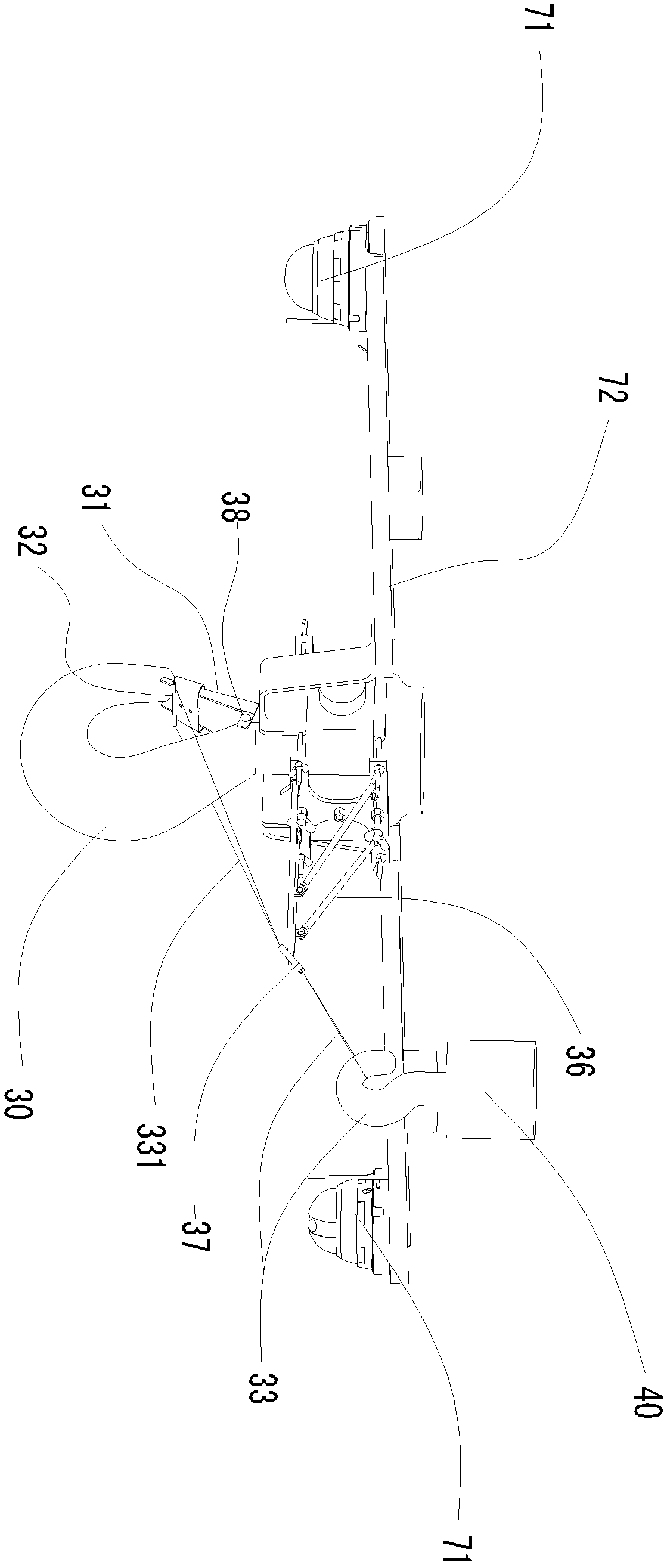
[0082] Such as figure 2 , image 3 and Figure 5 As shown, the hanger of the present invention includes a first hook 30 provided with a blocking device 31, wherein one end of the blocking device 31 is hinged to the first hook 30, and the other end of the blocking device 31 is connected to the opening end 34 of the first hook. The inner connection, that is, the inner side of the first hook opening end 34 limits the blocking device 31 to its inner side. An elastic reset device 38 is arranged between the blocking device 31 and the first hook 30 . The elastic reset device 38 here is a torsion spring, which can push the movable end of the blocking device 31 to the inner side of the opening end 34 of the first hook for compression. A flexible traction device 33 is disposed between the blocking device 31 and the first hook 30 , and the flexible traction device 33 stretches the blocking device 31 along the inner side of the first hook 30 . Flexible traction device 33 comprises tra...

Embodiment 2

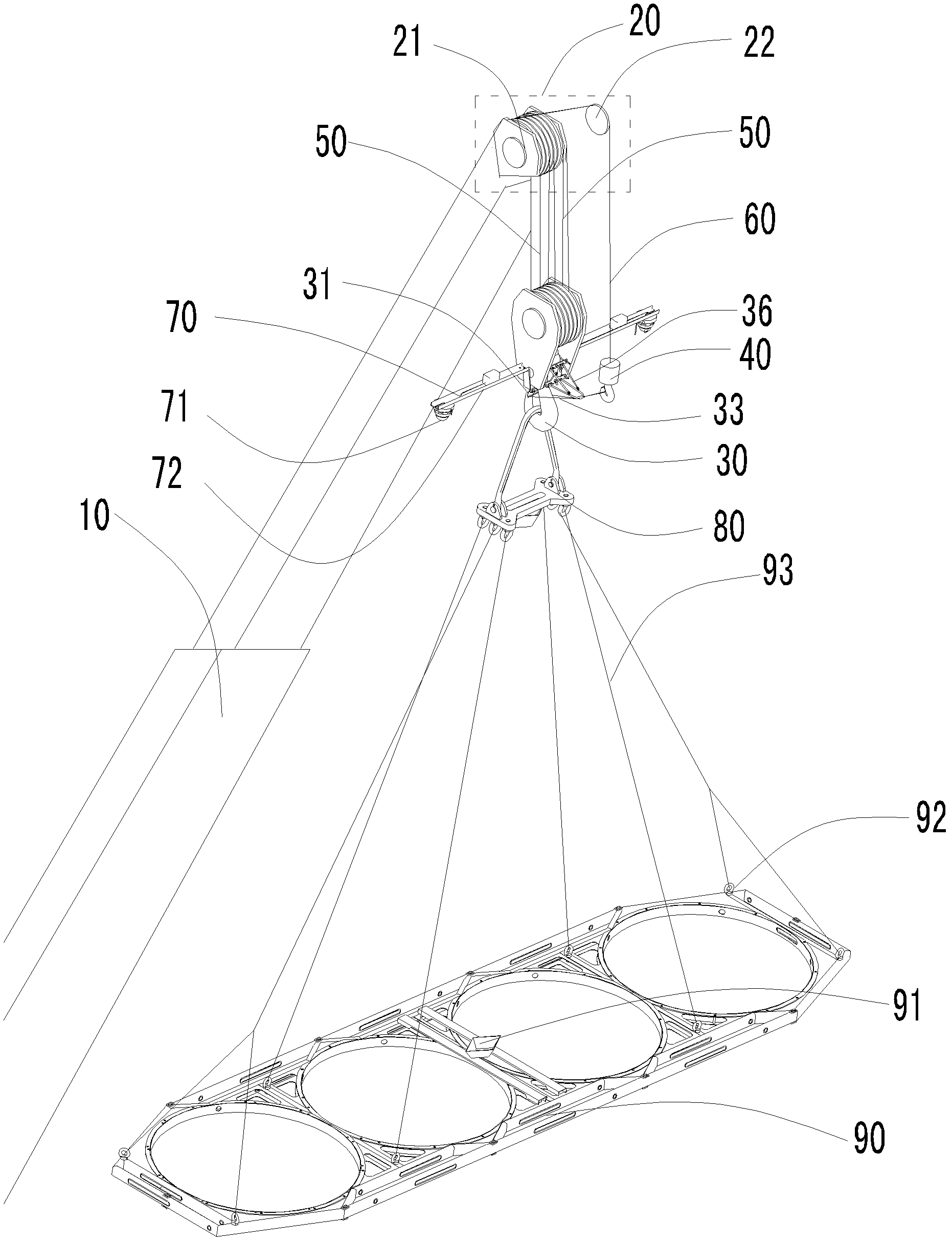
[0084] Such as Figure 1 to Figure 6 As shown, the flexible traction device 33 includes a second hook 40 and a traction rope 331, the traction rope 331 is sleeved in the second hook 40, and the first hook neck 35 is located at the opening end of the second hook 40 and the first hook. 34, the first hook 30 and the second hook 40 are suspended on the support arm 10, the support arm 10 is provided with a pulley block 20, the pulley block 20 is arranged on the top of the support arm 10, and the pulley block 20 includes the first pulley 21 and The second pulley 22, the first pulley 21 and the second pulley 22 are all arranged on the support arm 10, the first suspension hook 30 is suspended below the first pulley 21 by the first suspension rope 50, and the first suspension hook 30 passes through the first The suspension rope 50 is connected with the first pulley 21 in the form of a movable pulley, and the height of the first suspension hook 30 can be adjusted through the first suspe...

Embodiment 3

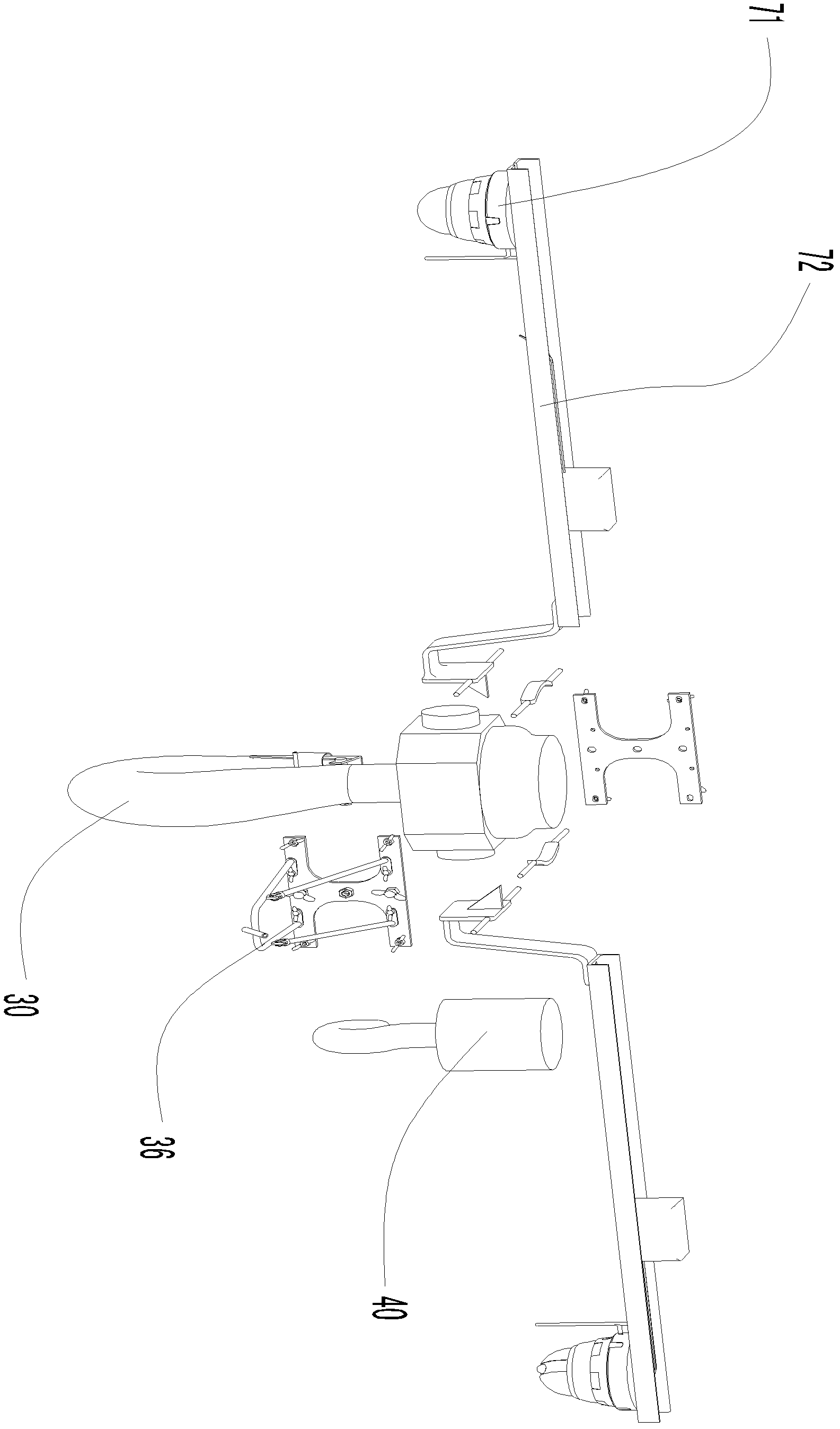
[0087] Such as Figure 1 to Figure 6 As shown, the first suspension hook 30 is provided with a camera assembly 70, the camera assembly 70 includes a camera 71 and a connecting rod 72 for fixing the camera 71, the camera 71 is arranged on both sides of the first suspension hook 30 through the connecting rod 72, connected Rod 72 is fixed on both sides of the first suspension hook 30, and is used for monitoring the operating condition of the spreader, so that the operator can know in time, and the camera 71 is movably connected with the end of the connecting rod 72, so that the camera 71 can do 360° on the horizontal plane. rotate.

[0088] Lifting ring assembly 80 is hoisted on the first suspension hook 30, and lifting ring assembly 80 comprises base body 81 and the suspension ring 82 that is arranged on base body 81 bottom, is hinged with lifting ring 83 on base body 81, makes base body 81 can rotate in horizontal direction, and suspension ring 82 It is arranged on both sides ...


PUM


Abstract

The invention relates to a lifting appliance, which comprises a blocking device, a first lifting hook and a flexible traction device, wherein one end of the blocking device is hinged with the first lifting hook, and the other end of the blocking device is connected with the inner side of the opening end of the first lifting hook; the flexible traction device is connected with the blocking device and drags the blocking device along the direction of the inner side of the first lifting hook; the blocking device is stretched towards the inner side of the first lifting hook by the flexible traction device to offset the tensile force of an elastic position restorating device, and the blocking device is pulled out of the inner side of the first lifting hook to form a space in which a rope is sleeved, so that hooking and hook take-up are implemented; and the blocking device can be operated remotely by the flexible traction device, so the cost is low, and operating personnel are not needed to perform manual operation by climbing nearby the first lifting hook during operation. Therefore, the lifting appliance is convenient to operate and high in efficiency, and reduces potential safety hazards of the operating personnel due to overhead operation.

Description

technical field [0001] The invention relates to a sling, in particular to a sling for working at heights above 10m. Background technique [0002] Hoisting machinery is a mechanical equipment that works in an intermittent cycle and completes the transportation and hoisting of heavy objects through the four major mechanisms of lifting, luffing, turning, and walking. The spreader is an indispensable and necessary part of the hoisting machinery. Its work The content is to hang the steel wire rope that binds the heavy objects to lift the heavy objects. The most commonly used sling is the hook, which is a sling with a hook-shaped end. The end that can be inserted into the cable is the open end of the hook. [0003] In order to prevent the rope that binds the heavy object from falling off the hook during the lifting process, there is usually an elastic and resettable blocking device on the hook. The blocking device is integrated with the open hook in a natural state. Forming a cl...

Claims


Application Information

Patent Timeline
IPC IPC(8): B66C1/14B66C1/16B66C1/40
Inventor 王明社何萌刘宣国钟萍萍
Owner HONGHUA OIL & GAS ENG SERVICE SICHUAN
Learn More