Telescopic system for crane boom and jib

A technology of boom and jib, which is applied in the field of boom telescopic system to achieve cost saving, high payload and weight reduction

Active Publication Date: 2012-07-04
MANITOWOC CRANE GROUP FRANCE
View PDF8 Cites 8 Cited by
  • Summary
  • Abstract
  • Description
  • Claims
  • Application Information

AI Technical Summary

Problems solved by technology

The disadvantage here is that the additional telescopic element has to be smaller than the end telescopic element of the main arm and guides or slides have to be taken into account during assembly

Method used


Image

  • Telescopic system for crane boom and jib
  • Telescopic system for crane boom and jib
  • Telescopic system for crane boom and jib

Examples


Embodiment Construction

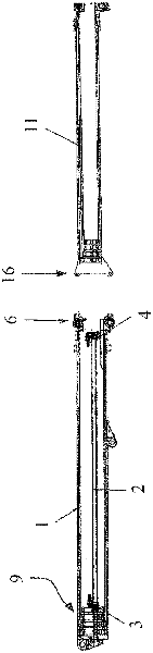
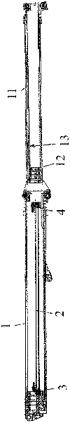
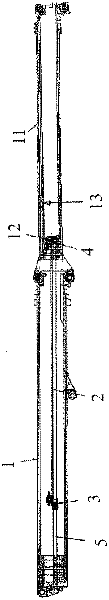
[0020] figure 1 And the jib system shown in other drawings includes a main jib 1 and an auxiliary jib 11 . The base 9 of the main boom 1 is pivotally connected (not shown) to the superstructure of a crane, in particular a mobile crane or a truck crane, which, in addition to the outer base portion or bottom of the main boom 1, includes a The four telescopic parts protruding, the four telescopic parts are in figure 1 not indicated separately. The auxiliary arm 11 also includes four telescopic parts that can be stretched out, figure 1 In , the connecting piece 6 of the head of the inner telescopic piece of the main arm 1 and the connecting piece 16 of the root of the outer telescopic piece of the auxiliary arm 11 are additionally indicated. Incidentally, the connection piece 6 is the same as, for example, the connection piece used to connect the luffing jib to the main boom 1 .

[0021] in addition, figure 1 Shown in the telescopic cylinder 2, the telescopic cylinder 2 i...


PUM


Abstract

The invention relates to a crane jib telescoping system for a telescopic crane jib which comprises a telescopic main jib (1) and telescopic auxiliary jib (11), comprising at least one telescoping cylinder (2) and a first telescopic part locking unit (3) which is arranged in the base portion of the telescoping cylinder (2), wherein a second telescopic part locking unit (4) is arranged on the telescoping cylinder (2) for telescoping the auxiliary jib (11) above the first telescopic part locking unit (3). It also relates to a crane jib system comprising a telescopic main jib (1) and a telescopic auxiliary jib (11) and comprising such a telescoping system, using the second telescopic part locking unit (4) of which the auxiliary jib can be telescoped in and out.

Description

technical field [0001] The invention relates to a boom telescoping system for a telescoping boom having a telescoping main boom and a telescoping jib. The telescoping system comprises at least one telescoping cylinder and a first telescoping locking unit arranged at the bottom of the telescoping cylinder. Background technique [0002] Telescoping systems with telescoping cylinders are basically known; for example a telescoping system is described in EP943580B1. Wherein, the telescopic cylinder is used to extend and retract the telescopic element or telescopic part of the main arm. [0003] Basically, such cranes are also known in which the jib is connected to the main jib. Application of the invention is particularly useful in mobile or truck cranes, luffing jibs are often attached to the forwardmost portion of the main jib for greater height and reach. Since such a luffing jib, which is mainly formed as a grid element, is assembled on the ground and is then aligned by th...

Claims


Application Information

Patent Timeline
Patent Type & Authority Applications(China)
IPC IPC(8): B66C23/693B66C23/70
CPCB66C23/708B66C23/64B66C23/68
Inventor D·斯图尔沃特
Owner MANITOWOC CRANE GROUP FRANCE
Why Eureka
Try Eureka