Unit ratio sequence-type transmission mechanism capable of being independently controlled

An independent control and unit ratio technology, applied in the direction of transmission, gear transmission, mechanical equipment, etc., can solve the problem of reducing transmission efficiency and achieve the effect of improving energy transmission efficiency

Inactive Publication Date: 2012-07-04
SUN YAT SEN UNIV
View PDF6 Cites 0 Cited by
  • Summary
  • Abstract
  • Description
  • Claims
  • Application Information

AI Technical Summary

Problems solved by technology

However, the gearbox structure is provided with the slide block, and the slide block will inevitab

Method used


Image

  • Unit ratio sequence-type transmission mechanism capable of being independently controlled
  • Unit ratio sequence-type transmission mechanism capable of being independently controlled
  • Unit ratio sequence-type transmission mechanism capable of being independently controlled

Examples


Embodiment Construction

[0045] In order to fully understand the present invention, preferred embodiments are exemplified below and described in detail with accompanying drawings, which are not intended to limit the scope of protection of the present invention.

[0046] The unit ratio sequence type independently controllable transmission mechanism of the preferred embodiment of the present invention can be applied to various technical fields related to mechanical variable speed transmission, such as: marine generators, wind power generators or transmission gearboxes for hybrid vehicles, etc., but it is not It is used to limit the scope of application of the independently controllable transmission mechanism of the present invention.

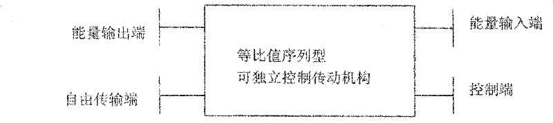
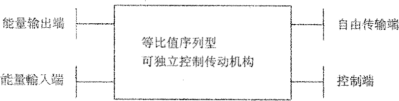
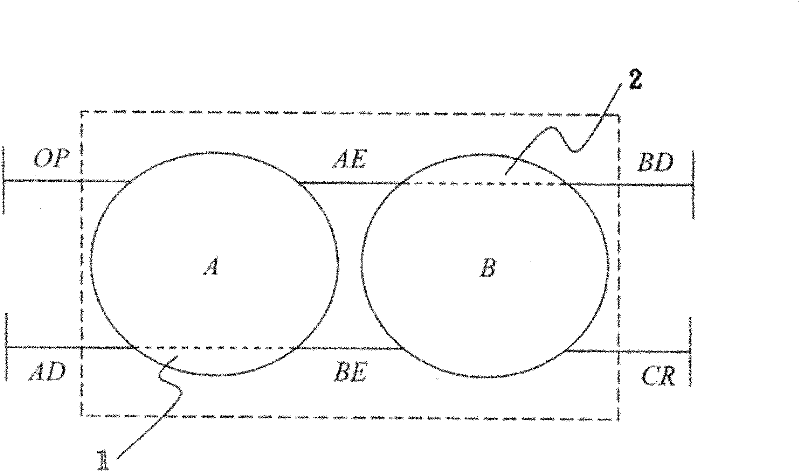
[0047] Figure 1A and 1B A schematic diagram of the unit ratio serial type independently controllable transmission mechanism revealing the first and second preferred embodiments of the present invention; Figure 2A and 2B Discloses the internal structure diagram of the ...


PUM


Abstract

The invention relates to a unit ratio sequence-type transmission mechanism capable of being independently controlled. The unit ratio sequence-type transmission mechanism comprises a first planetary gear set, a second planetary gear set, an energy input end and a free transmission end, wherein the first planetary gear set comprises an energy output end; the second planetary gear set is connected to the first planetary gear set and comprises a control end; the energy input end is arranged on the second planetary gear set; and the free transmission end is arranged on the first planetary gear set, controlled by the control end and used for freely switching the free transmission end to be used as one of the energy input end and an energy output end. The unit ratio sequence-type transmission mechanism disclosed by the invention has the beneficial effect of improving the energy transmission efficiency.

Description

technical field [0001] The invention relates to a transmission mechanism, in particular to an independently controllable transmission mechanism which can improve energy transmission efficiency. Background technique [0002] Existing transmission mechanisms, such as the gear box structure for vehicles of the Taiwan Patent Announcement No. I242521, disclose that a main shaft is provided with a slide block, and both sides of the slide block are provided with a forward gear and an afterburner gear. A connecting shaft is provided with a reverse slider, and the connecting shaft located on one side of the reverse slider is provided with a reverse bevel gear and a forward bevel gear, and the reverse bevel gear A final shaft is arranged between the forward bevel gear and the forward bevel gear, and the final shaft is driven by the shaft. The final shaft is located between the reverse bevel gear and the forward bevel gear, and the booster gear and the forward The gear is also located...

Claims


Application Information

Patent Timeline
IPC IPC(8): F16H1/28
Inventor 黄冠雄蔡得民林重琪光灼华陈遵立
Owner SUN YAT SEN UNIV
Why Eureka
Try Eureka