
Valve for vacuum process

一种真空工艺、阀体的技术,应用在升阀、阀细节、阀装置等方向,能够解决泵问题、减少装置使用寿命等问题

Active Publication Date: 2012-07-04
李东民
View PDF3 Cites 9 Cited by
  • Summary
  • Abstract
  • Description
  • Claims
  • Application Information

AI Technical Summary

Problems solved by technology

As a result, foreign substances are deposited inside the valve due to corrosive gases, which can reduce the life of the unit and even cause serious problems with the pump

Method used


Image

  • Valve for vacuum process
  • Valve for vacuum process
  • Valve for vacuum process

Examples


Embodiment Construction

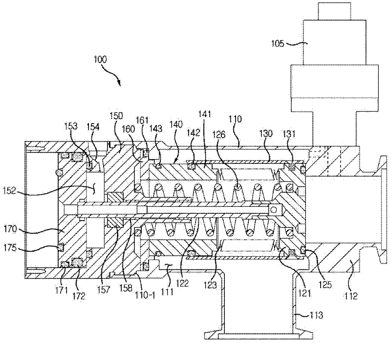
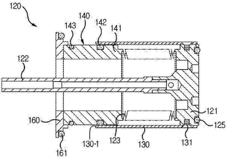
[0027] Hereinafter, a valve for a vacuum process according to an exemplary embodiment will be described in detail with reference to the accompanying drawings.

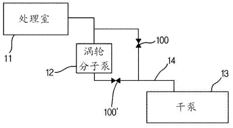
[0028] figure 1 is a schematic block diagram of a vacuum system using a valve for a vacuum process according to an exemplary embodiment. figure 1 A process chamber 11 , a turbomolecular pump (TMP) 12 and a dry pump 13 are shown.

[0029] When the gas in the chamber is energized to become a plasma state, a reaction occurs in the wafer in the chamber and a thin film is formed on the wafer. Excess reactants generated in the thin film forming process are discharged through the turbomolecular pump 12 and the pipe 14 . A first valve 100 for a vacuum process is installed between the process chamber 11 and the dry pump 13 . A second valve 100' for the vacuum process is installed downstream of the turbomolecular pump. The first valve 100 for a vacuum process may also be called an "isolation valve". The second valve 100' fo...


PUM


Abstract

Provided is a valve for vacuum process, including: a first valve body having an inlet port and an outlet port; a sealing unit configured to move forward to and backward from the inlet port so as to have a closed position and an open position; a shaft covered with a bellows, and configured to move the sealing unit between the closed position and the open position; a cover for shielding the bellows from corrosive gas when the sealing unit is in the open position; and a cover guide unit configured to guide the cover to move along the shaft.

Description

technical field [0001] The following description relates to a valve for a vacuum process that controls the degree of vacuum according to a stage in a semiconductor manufacturing process. Background technique [0002] Vacuum systems are used in the manufacture of semiconductor devices. In a chemical vapor deposition (CVD) system, when a gas in a chamber is energized to be in a plasma state, a reaction occurs in a wafer in the chamber, and a thin film is formed on the wafer. Excess reactants produced in the process are discharged through pumps and pipes. [0003] These vacuum systems include valves to control the vacuum level of the pumps and pipelines. As a result, foreign substances are deposited inside the valve due to corrosive gases, which can reduce the service life of the unit and even cause serious problems with the pump. Contents of the invention [0004] An object of an embodiment of the present invention is to provide a valve for a vacuum process that minimizes...

Claims


Application Information

Patent Timeline
Patent Type & Authority Applications(China)
IPC IPC(8): F16K1/00F16K27/02F16K41/10F16K31/122F16K51/02H01L21/67
CPCF16K41/10F16K51/02F16K31/122H01L21/67017
Inventor 李东民
Owner 李东民
Learn More