
Monomer deposition apparatus

A single monomer deposition and equipment technology, applied in the direction of electric solid devices, semiconductor devices, devices for coating liquid on the surface, etc., can solve the problems of shortened life cycle, increased maintenance cost, increased manufacturing cost, etc., to improve productivity and prolong Effects of maintenance cycle and manufacturing cost reduction

Inactive Publication Date: 2013-05-22
SNU PRECISION CO LTD
View PDF5 Cites 3 Cited by
  • Summary
  • Abstract
  • Description
  • Claims
  • Application Information

AI Technical Summary

Problems solved by technology

During maintenance, the process is stopped, and thus productivity is reduced
In addition, since the life cycle of members around the substrate other than the transfer unit is shortened, maintenance costs are increased, so that manufacturing costs are also increased

Method used


Image

  • Monomer deposition apparatus
  • Monomer deposition apparatus
  • Monomer deposition apparatus

Examples


specific Embodiment approach

[0017] Hereinafter, the present invention will be described more fully with reference to the accompanying drawings. Likewise, descriptions of well-known functions and configurations can be omitted to increase clarity and conciseness. The exemplary embodiments of the present invention described herein will be thought of by those skilled in the art. In the drawings, the sizes and relative sizes of layers and regions may be exaggerated for clarity.

[0018] Exemplary embodiments of the monomer deposition apparatus will be described in detail with reference to the accompanying drawings.

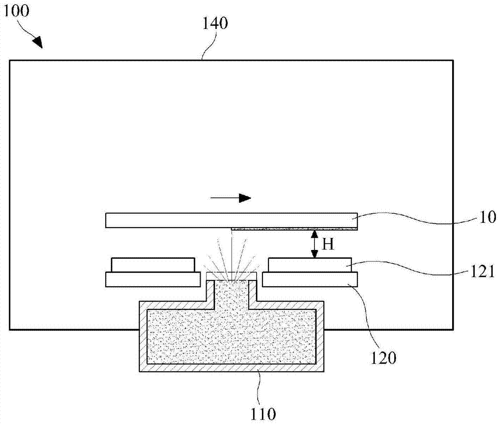
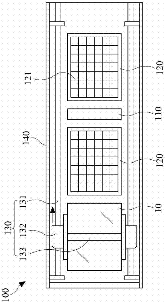
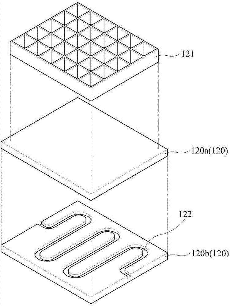
[0019] reference figure 1 with figure 2 , The monomer deposition apparatus 100 includes a chamber 140, a deposition unit 110, and a cooling plate 120.

[0020] The chamber 140 includes a processing space in which the substrate 10 can be accommodated, and the monomer is to be deposited in the substrate. The cavity 140 may be in the shape of a cylinder or a hexahedron. However, the shape of the cavit...


PUM


Abstract

Provided is a monomer deposition apparatus which minimizes the deposition of a monomer onto members around a substrate when the monomer is deposited onto the substrate. To this end, the monomer deposition apparatus includes a chamber defining a processing space in which the substrate is processed, and a deposition unit, at least one portion of which is received in the chamber and which is spaced a predetermined distance from the substrate so as to discharge the monomer onto the substrate. The monomer deposition apparatus further includes a cooling plate disposed adjacently to a circumference of the deposition unit such that there is no interference with the discharge of the monomer, the cooling plate being spaced a predetermined distance from the substrate to cool the monomer which is not deposited onto the substrate. Thus, since the monomer, which is not deposited onto the substrate, is cooled by the cooling plate, the deposition of monomer vapors onto members around the substrate may be minimized. Therefore, since the period for scheduled maintenance may be extended, productivity may be improved and manufacturing costs may be reduced.

Description

Technical field [0001] The following description relates to a monomer deposition apparatus, and more specifically to a monomer deposition apparatus for forming a protective layer for encapsulating an organic material deposited on a substrate. Background technique [0002] Generally, an organic light emitting diode (OLED) can be driven at a lower voltage than a conventional liquid crystal display device (LCD), and is superior to an LCD in terms of thinness, wide viewing angle, and high response rate. [0003] OLEDs can be classified into passive matrix OLEDs and active matrix OLEDs. In passive matrix OLEDs, there is no switching device in each pixel. In active matrix OLEDs, thin film transistors are used to form each pixel. The switching device. In the structure of the active matrix OLED, an organic light emitting part is formed on a substrate, the organic light emitting part is encapsulated, and the organic light emitting part formed of an organic material is not in contact with o...

Claims


Application Information

Patent Timeline
Patent Type & Authority Applications(China)
IPC IPC(8): H01L51/56C23C14/12
CPCC23C14/564C23C14/12B05D1/60
Inventor 尹亨硕南宫晟泰李泰成朴一濬
Owner SNU PRECISION CO LTD
Learn More