Control method for air assisting type gas drive SCR system

An SCR system, air-assisted technology, applied in air quality improvement, exhaust treatment, exhaust devices, etc., can solve problems such as large time consumption, pressure shock, urea solution pressure shock, etc., to achieve clear status functions and clear control logic , the effect of improving reliability and maintenance cycle

Inactive Publication Date: 2018-02-13
广州贻谷环保科技有限公司
View PDF3 Cites 20 Cited by
  • Summary
  • Abstract
  • Description
  • Claims
  • Application Information

AI Technical Summary

Problems solved by technology

[0004] In the prior art, the urea pressure building pump is used as the main source of power for injecting urea in the SCR system. Since the motor stroke of the urea pump is small, a relatively high rotational speed is required to build up the pressure; Precisely control the pressure to keep the pressure stable. The rapid back and forth movement of the urea pump diaphragm will cause the pressure oscillation of the urea solution, and the rapid switching of high / low speed in a short period of time will also cause pressure oscillations, so complex control strategies and mechanical structures are required to eliminate these pressure shocks and keep the pressure relatively stable
[0005] In addition, the motor in the urea pressure building pump is a high-precision component, and the cost is very high. Its calibration and subsequent maintenance are also relatively complicated, and the requirements for the working environment are also high.
In addition, in order to ensure that the urea in the urea pump body and urea pipe is cleaned after the urea injection is completed, it is necessary to design a complex reversing valve or a complex control logic to achieve it. Once the system fails, due to the complexity of the system, it is necessary to It takes a lot of time for professionals to conduct inspection and maintenance; the cost is very high, and in the aftermarket, the maintenance cost of urea pumps remains high

Method used


Image

  • Control method for air assisting type gas drive SCR system
  • Control method for air assisting type gas drive SCR system
  • Control method for air assisting type gas drive SCR system

Examples


Embodiment Construction

[0030] The technical solution of the control method of the air-assisted gas drive SCR system involved in the present invention will be described in further non-limiting detail below in conjunction with preferred embodiments and accompanying drawings.

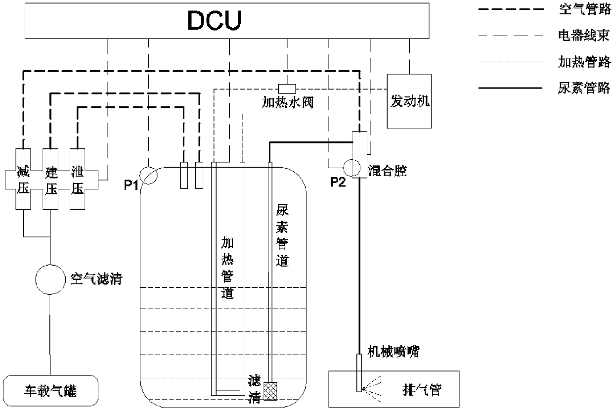
[0031] see figure 1 As shown, the air-assisted gas-driven SCR system (hereinafter referred to as "the system") involved in the present invention is an SCR system that uses compressed air as the power source of the system, replacing the urea pressure building pump in the traditional sense. The whole system is mainly composed of a urea tank assembly, a mixing chamber and an air solenoid valve assembly, and has a simple structure, and uses the control method involved in the present invention to achieve better functions.

[0032] In the system, the vehicle-mounted air tank is used as the compressed air source, and the function of the air filter is to filter the compressed air to ensure its cleanliness. The air solenoid valve assemb...


PUM


Abstract

The invention discloses a control method for an air assisting type gas drive SCR system. The air assisting type gas drive SCR system comprises an initial state, a heating state, a pressure building state, an injection state, a pressure releasing state and a purging state. In the injection state of the system, a urea metering valve is used for conducting accurate control over the urea solution flow, vehicle-mounted compressed air is used for pressurizing the urea solution in a urea tank, and the pressurized urea solution is metered through the metering valve and then injected into a mixing cavity; and then, the other path of compressed air of the mixing cavity conveys the metered urea solution to a mechanical urea nozzle, the urea solution enters an exhaust pipe and is subjected to the chemical reaction with NOx in engine exhaust gas in a catalytic converter, and the purpose of exhaust gas purifying is achieved.

Description

technical field [0001] The invention relates to a control method of an air-assisted gas drive SCR system. Background technique [0002] Selective Catalytic Reduction (SCR) technology is a technology to reduce NOx in diesel vehicle exhaust emissions, that is, under the action of a catalyst, the reducing agent ammonia or urea is injected into the exhaust pipe to reduce NOx in the exhaust gas to N2 and H2O to achieve the purpose of eliminating NOx. [0003] The existing technical solutions are mainly divided into air-assisted SCR system and non-air-assisted SCR system. Its main structure includes urea pressure building pump, urea nozzle, urea tank assembly and other components. The speed of the motor is used to build and stabilize the pressure of the urea solution, and the urea injection volume is accurately metered by controlling the duty ratio of the metering valve. After the urea injection is finished, it is necessary to use the positive and negative rotation of the motor ...

Claims


Application Information

Patent Timeline
Patent Type & Authority Applications(China)
IPC IPC(8): F01N3/20
CPCF01N3/2006F01N3/208F01N2610/146Y02A50/20Y02T10/12
Inventor 彭小飞许新曹文浩
Owner 广州贻谷环保科技有限公司
Why Eureka
Try Eureka