Heat pipe with grooves

A heat pipe and grooved technology, applied in the field of grooved heat pipes, can solve the problems that the efficiency of sintered heat pipes cannot be achieved, the working liquid channel of the finished heat pipe becomes smaller, and the advantage of low cost cannot be expanded, so as to reduce heat conduction The resistance value, the specific surface area of ​​the powder increase, and the effect of improving the contact surface

Inactive Publication Date: 2012-07-04
KUN SHAN DOTOP METAL TECH CO LTD
View PDF7 Cites 0 Cited by
  • Summary
  • Abstract
  • Description
  • Claims
  • Application Information

AI Technical Summary

Problems solved by technology

Similarly, if the width of the top of the groove is greater than the particle size of the copper powder, the copper powder will also fall to the bottom of the groove, and the working liquid channel of the finished heat pipe formed by it will also be significantly smaller.
resulting in a loss of performance
[0006] Therefore, low cost also has its disadvantages, that is, these grooved heat pipes cannot achieve the performance of sintered heat pipes due to the limitations of their structure and physical properties.
It cannot be used in products with high power requirements or in environments with harsh working conditions
Therefore, it is impossible to expand its low-cost advantage to a wider field

Method used


Image

  • Heat pipe with grooves
  • Heat pipe with grooves
  • Heat pipe with grooves

Examples


Embodiment Construction

[0023] The present invention will be described in detail below with reference to the accompanying drawings and in combination with embodiments.

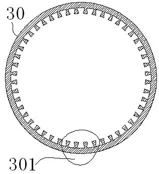
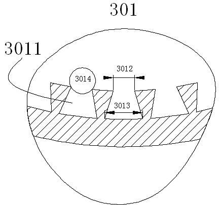
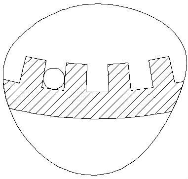
[0024] see figure 1 , Figure 5 As shown, a grooved heat pipe includes a pipe body 30, the inner wall of the pipe body 30 is provided with a plurality of groove structures in the radial direction as a working fluid circuit 3011, and the pipe body 30 is filled with copper powder Particles 3014 are sintered to form a copper powder layer. The cross-section of the groove structure is a trapezoidal structure. The width of the top 3012 of the groove structure is smaller than the width of the bottom 3013 of the groove, and the top 3012 of the groove is The width is smaller than the average particle diameter of the copper powder particles 3014.

[0025] Preferably, the average width dimension from the slot top 3012 to the slot bottom 3013 of the groove structure is ≥ the average particle diameter of the copper powder particles 3014 .

[...


PUM


Abstract

The invention discloses a heat pipe with grooves, which comprises a pipe body. A plurality of groove structures which are used as actuating liquid loops are arranged on the pipe body along the radial direction of the inner wall of the pipe body, copper powder particles are filled in the pipe body and are sintered to form a copper powder layer, the section of each groove structure is a trapezoidal structure, and the width of the top of a notch of each groove structure is smaller than that of the bottom of the notch, and is smaller than the average particle size of the copper powder particles. The tops of the notches of actuating liquid loops of the heat pipe with the grooves are far narrower than the bottoms of the notch, accordingly, the copper powder particles cannot fall into the groove structures to block the actuating liquid loops when filled into the pipe, content of actuating liquid in the groove structures is improved, and maximum heat transfer quantity is increased.

Description

technical field [0001] The invention relates to a heat pipe, in particular to a grooved heat pipe. [0002] Background technique [0003] The grooved heat pipe used in the existing heat sinks of electronic products is more and more welcomed by some manufacturers because of its low cost, and has become their main product. [0004] see image 3 As shown, it is a partial cross-sectional view of an ordinary H-shaped pipe. The tank body is approximately rectangular in shape, and the width of the tank top is equal to that of the tank bottom. At the bottom, the width of the groove can only be smaller than the particle size of the copper powder, so that the working liquid channel of the finished heat pipe made of this type of pipe is seriously reduced, and the efficiency of the heat pipe is greatly reduced. [0005] see Figure 4 As shown, it is a partial cross-sectional view of a V-shaped copper pipe. The groove body is in a triangular shape, and the bottom of the groove is almo...

Claims


Application Information

Patent Timeline
Patent Type & Authority Applications(China)
IPC IPC(8): F28D15/04
Inventor 朱胜利
Owner KUN SHAN DOTOP METAL TECH CO LTD
Why Eureka
Try Eureka