
Heat dissipation module

A technology of heat dissipation module and heat pipe, which is used in cooling/ventilation/heating transformation and other directions

Inactive Publication Date: 2015-02-25
ASIA VITAL COMPONENTS SHENZHEN CO LTD
View PDF4 Cites 0 Cited by
  • Summary
  • Abstract
  • Description
  • Claims
  • Application Information

AI Technical Summary

Problems solved by technology

[0006] Generally, the heat generated by the chip is concentrated on the surface, but the heat distribution on the surface may be inconsistent. This is due to the distribution of the integrated components in the chip. Improving the efficiency of heat conduction and effectively solving the heat dissipation problem of high-power electronic components is what the industry needs to improve at present.

Method used


Image

  • Heat dissipation module
  • Heat dissipation module
  • Heat dissipation module

Examples


Embodiment Construction

[0056] Below in conjunction with accompanying drawing and specific embodiment the present invention is described in further detail:

[0057] The above-mentioned purpose of the present invention and its structural and functional characteristics will be described according to the preferred embodiments of the accompanying drawings.

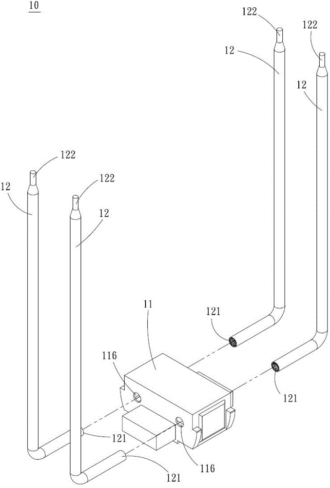
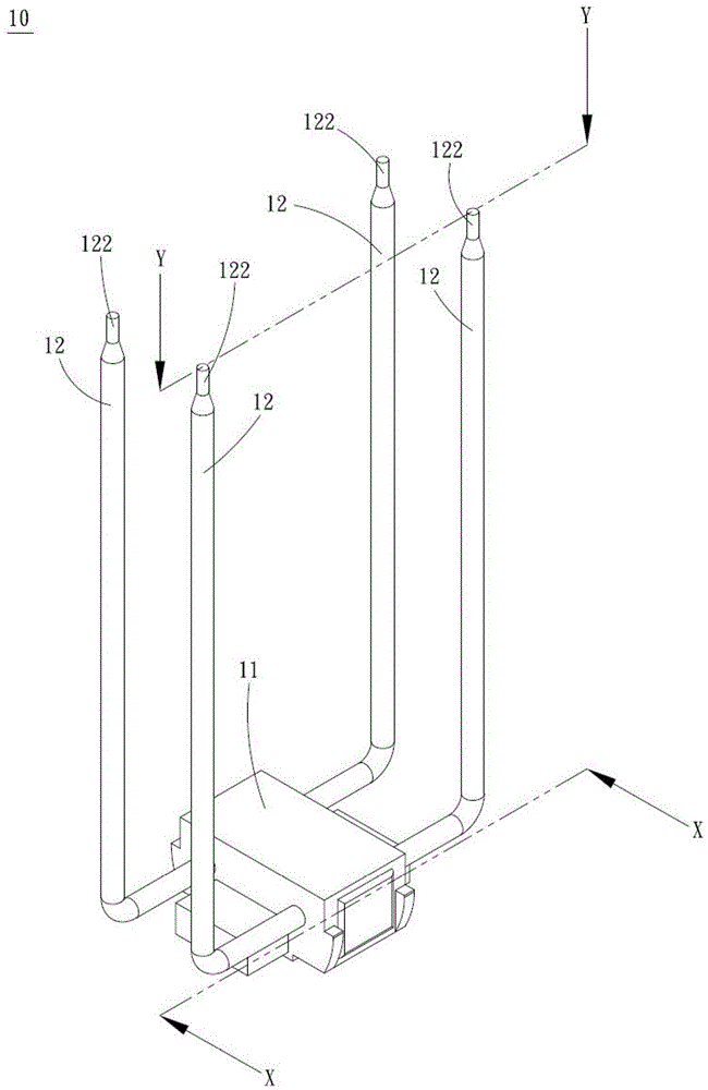
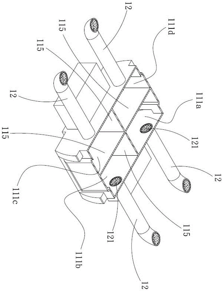
[0058] see Figures 1 to 4 , figure 1 It is a three-dimensional exploded schematic diagram of the present invention, figure 2 It is a three-dimensional combination schematic diagram of the present invention, image 3 for the invention figure 2 The cross-sectional view of the X-X line, Figure 4 for the invention figure 2 The profile of the Y-Y line. Such as Figures 1 to 4 As shown, the heat dissipation module 10 includes a casing 11, and the casing 11 includes a plurality of casing chambers 111a-111d that are independent from each other. An open end of at least one heat pipe is communicated with, and the open end is communicated with a he...


PUM


Abstract

A heat dissipation module comprises a shell, a plurality of independent shell cavities are arranged in the shell and not communicated with one another, each shell cavity is communicated with one open end of at least one heat pipe, the open ends are communicated with heat pipe cavities in the heat pipes, and the independent cavities are communicated with the heat pipe cavities.

Description

technical field [0001] The invention relates to a heat dissipation module, in particular to a heat dissipation module that dissipates heat from heat sources that generate different amounts of heat. Background technique [0002] As the current electronic equipment is gradually advertised as light and thin, the size of each component must be reduced accordingly. However, the heat generated by the size reduction of electronic equipment has become the main obstacle to improving the performance of electronic equipment and systems. Therefore, in order to effectively solve the heat dissipation problem of components in electronic equipment, the industry proposes vapor chambers and heat pipes with better heat conduction performance to effectively solve the current heat dissipation problem. [0003] The uniform temperature plate (Vapor chambef system includes a rectangular shell and the capillary structure of the inner chamber wall of the shell, and the inside of the shell is filled w...

Claims


Application Information

Patent Timeline
IPC IPC(8): H05K7/20
Inventor 杨修维
Owner ASIA VITAL COMPONENTS SHENZHEN CO LTD
Learn More