Method and system for machine condition monitoring

A technology for monitoring systems and machines, applied in general control systems, test/monitor control systems, testing of machines/structural components, etc., and can solve problems such as inability to identify or track

Inactive Publication Date: 2012-07-04
GENERAL ELECTRIC CO
View PDF5 Cites 15 Cited by
  • Summary
  • Abstract
  • Description
  • Claims
  • Application Information

AI Technical Summary

Problems solved by technology

Difficulty identifying the most degraded machines or those requiring immediate attention
Additionally, the effect of intermittent maintenance actions such as filter cleaning, lubrication, etc. cannot be identified or tracked until the next inspection

Method used


Image

  • Method and system for machine condition monitoring
  • Method and system for machine condition monitoring
  • Method and system for machine condition monitoring

Examples


Embodiment Construction

[0011] By way of illustration and not limitation, the following detailed description illustrates embodiments of the invention. It is contemplated that the present invention has general application to analytical and method embodiments for monitoring remaining life of machines in industrial, commercial, and residential applications.

[0012] As used herein, an element or step recited in the singular followed by the indefinite article "a" or "a" should be understood as not excluding plural elements or steps, unless such exclusion is explicitly stated. Furthermore, references to "one embodiment" of the present invention are not to be interpreted as excluding the existence of additional embodiments that also incorporate the recited features.

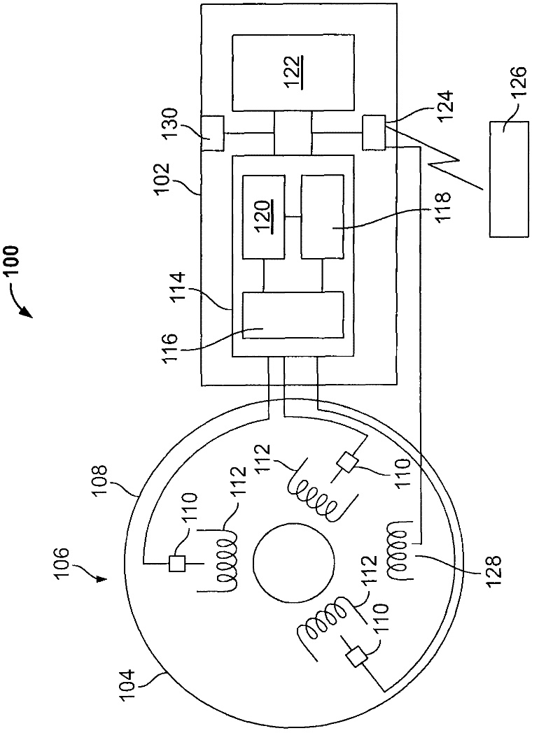
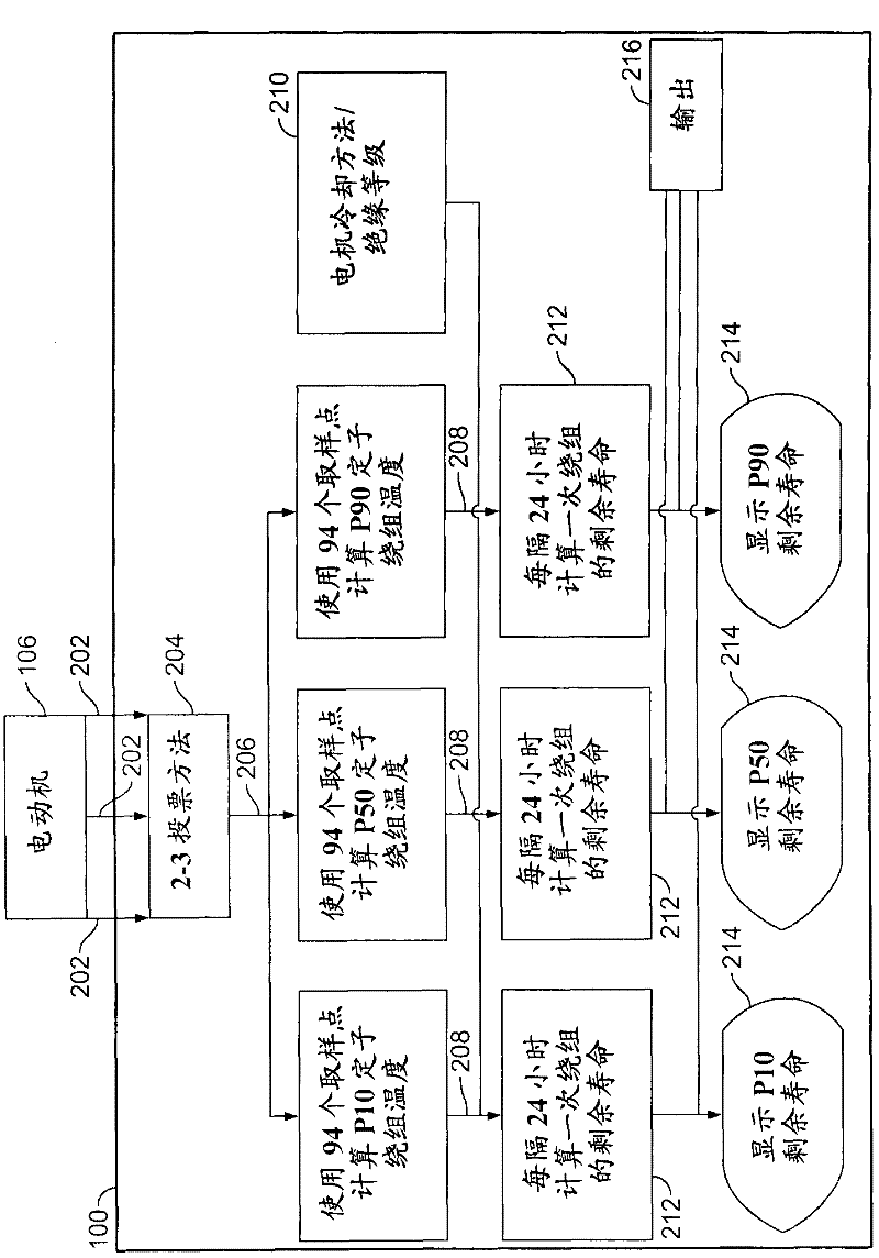
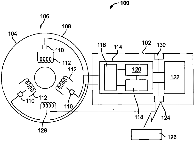
[0013] Embodiments of the present invention include a machine-mounted life calculator that provides a user with an indication of the remaining life of a machine component such as, but not limited to, a motor stator winding. This calculator c...


PUM


Abstract

A machine monitoring system (100) is provided. The system includes a housing (102) mounted to a surface (108) of a machine (106), a plurality of sensors (110) configured to monitor a parameter of the machine and generate respective output signals (202), the parameter indicative of a condition of the machine, a voting module (116) positioned within the housing and configured to receive the respective output signals and generate a corrected output (206) based on the respective output signals, a memory device (118) positioned within the housing and including a store location configured to store manual input functions (210) relating to a construction of the machine, a life calculator (120) positioned within the housing and communicatively coupled to the voting module and the memory device, the life calculator configured to determine a life remaining in the machine using the corrected output and the manual input functions, and a display (122) positioned within the housing and configured to display (214) the life remaining in the machine.

Description

technical field [0001] The field of the invention relates generally to machine condition monitoring, and more particularly to methods and systems for monitoring the remaining life of a machine in near real time using the monitored condition of the machine. Background technique [0002] In at least some known industries (such as, but not limited to, the oil, gas, and electric industries), critical equipment must operate at its maximum capacity during periods of peak demand in order to benefit from specified market conditions, e.g. The price of electricity and the price of electricity per kilowatt-hour are higher. [0003] Based on available data, one of the top causes of equipment unavailability is downtime due to scheduled maintenance. Often, such maintenance is not required by the condition of the equipment, but is dictated by timing requirements. By enabling condition-based maintenance, non-value-added inspections and maintenance can be reduced, if not completely elimina...

Claims


Application Information

Patent Timeline
Patent Type & Authority Applications(China)
IPC IPC(8): G01M99/00G01R31/34
CPCG05B19/4065G05B23/0224G05B2219/37209
Inventor R·B·纳加蒂尔M·T·小罗宾逊
Owner GENERAL ELECTRIC CO
Why Eureka
Try Eureka