Micro-mirror graph scanning mechanism

A graphic scanning and micromirror technology, used in medical science, optics, instruments, etc., to achieve the effects of high safety, low power consumption, and simple optical path

Active Publication Date: 2012-07-04
无锡微文半导体科技有限公司
View PDF4 Cites 6 Cited by
  • Summary
  • Abstract
  • Description
  • Claims
  • Application Information

AI Technical Summary

Problems solved by technology

[0004] Although there are some relatively mature control schemes in the field of MEMS micromirrors, there is no system scheme that integrates micromirror property testing and graphic scanning schemes in the field of electrothermal micromirrors, especially low-cost and high-security control schemes. Program

Method used


Image

  • Micro-mirror graph scanning mechanism
  • Micro-mirror graph scanning mechanism
  • Micro-mirror graph scanning mechanism

Examples


Embodiment Construction

[0042] The following is an embodiment of a thermally driven micromirror of the micromirror pattern scanning mechanism.

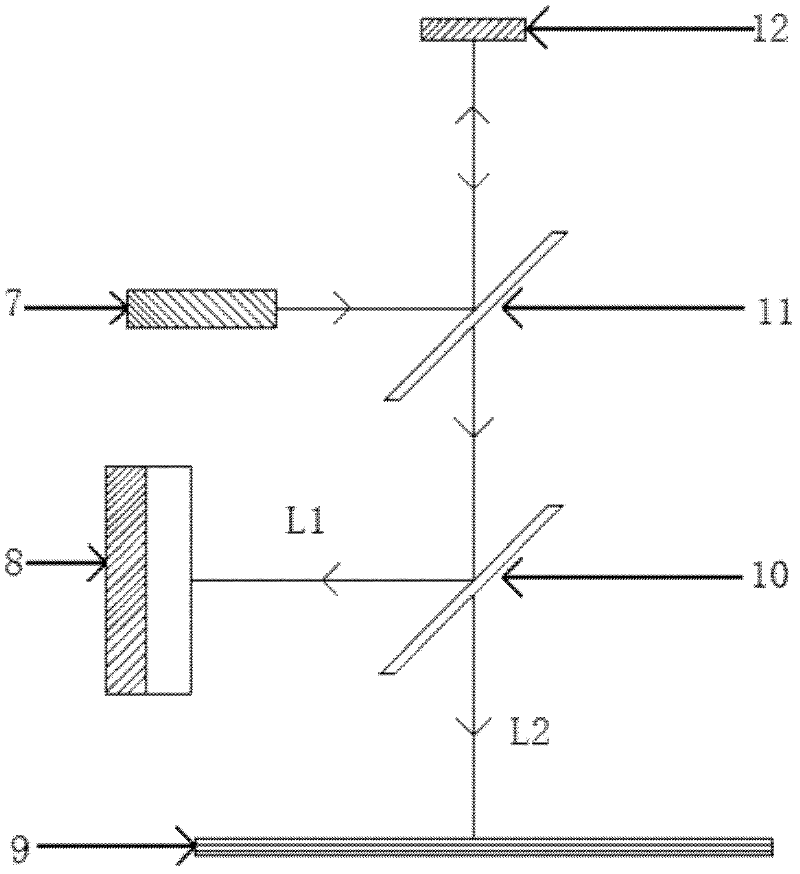
[0043] Such as figure 2 The optical path is constructed in a manner, and the optical path structure includes a laser light source 7 , two optical mirrors, a heat-driven micromirror device 12 and a screen 9 . The laser light source 7 is divided into two laser beams after passing through the first beam splitter 11, one beam is hit on the heat-driven micromirror device system 12, and the other beam is hit on the second beam splitter 10, and the two beams of light separated by the second beam splitter are one One beam hits the position sensitive sensor PSD 8 and one hits the screen 9 .

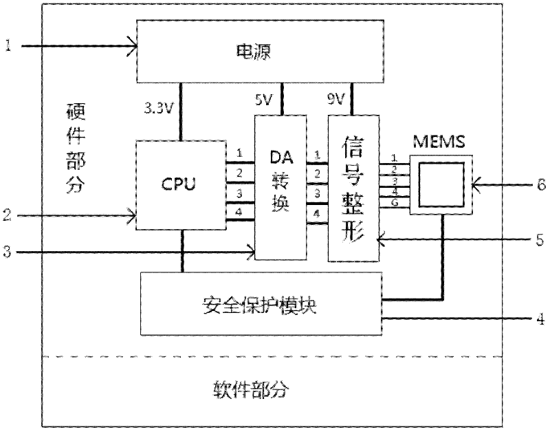
[0044] To realize optical scanning, the drive circuit must first generate an analog drive signal. The block diagram of the entire thermally driven micromirror device 12 system is shown in figure 1 As shown, the driving circuit includes a central processing unit 2 , a digital-...


PUM


Abstract

The invention discloses a micro-mirror graph scanning mechanism, which comprises a laser light source, spectroscopes, a micro-mirror device and a screen and is characterized by further comprising a position sensitive detector. The spectroscopes are divided into two groups and are respectively a first spectroscope and a second spectroscope. The second spectroscope is used for dividing laser emitting by the first spectroscope into two beams and respectively emits the beams to the screen and the position sensitive detector. The position sensitive detector and the second spectroscope form feedbacks, the deformation of a graph is rectified according to scanned graphs displayed on the position sensitive detector and the screen, and the properties of the micro-mirror are tested. The micro-mirror graph scanning mechanism integrates the test of the properties and the scanning of the graphs into a whole so as to facilitate understanding of the properties and relative application of the micro-mirror device. The deformation of the graphs can be rectified by utilizing the position sensitive detector (PSD) and the spectroscope to form the feedbacks for loop control, and an optical path is simple.

Description

technical field [0001] The invention belongs to the technical field of medical equipment, in particular to a micromirror pattern scanning mechanism. Background technique [0002] Micro-electro-mechanical systems (MEMS for short) is a three-dimensional device manufactured by micro-machining technology, including at least one movable structure to satisfy a certain mechanical action. MEMS devices are used in many different fields because they borrow the technology of integrated circuits. More and more sensors and actuators in this century tend to adopt MEMS technology, among which microelectromechanical system micromirrors are one example. The force generated by the MEMS-actuated structure is small but sufficient to drive the deflection of the mirror. Among the many MEMS micromirrors, the electrothermal micromirror is a microelectromechanical system that deflects the mirror by thermal deformation. The electrothermal micromirror system mainly includes three parts: the mirror ...

Claims


Application Information

Patent Timeline
Patent Type & Authority Applications(China)
IPC IPC(8): G02B26/10A61B5/00
Inventor 兰树明谢会开
Owner 无锡微文半导体科技有限公司
Why Eureka
Try Eureka