
Eureka
For R&D, Eureka makes reading and utilizing patents & technical documents easy.
Eureka AIR
Designed for self-driven R&D workflows. Generate viable solutions, solve complex R&D challenges, empower your innovation with AI.

Eureka Materials
Designed for material experts only. Revolutionize your material R&D, from search, analyze, to developing new materials.

TechResearch
Generate reliable direction feasibility study reports for your R&D in just a few steps.

TechSeek
Discover and master advanced knowledge NOW. Basics, ideas, possibilities, all at once.

TechMind
As an expert in R&D Theories, TechMind can generates customized viable solutions instantly.

TechRisk
Analyze your overall solution with one click, know your potential R&D risks in advance.

TechMonitor
Get weekly tech updates, stay abreast of the latest tech innovations and key insights.
Squirrel-cage type motor stator
A motor stator and squirrel-cage technology, applied to asynchronous induction motors, electrical components, electromechanical devices, etc., can solve the problem of no protection measures for leakage current
- Summary
- Abstract
- Description
- Claims
- Application Information
AI Technical Summary
Problems solved by technology
Method used
Image

Examples
Embodiment Construction
[0013] Below in conjunction with accompanying drawing, the present invention is described in further detail:
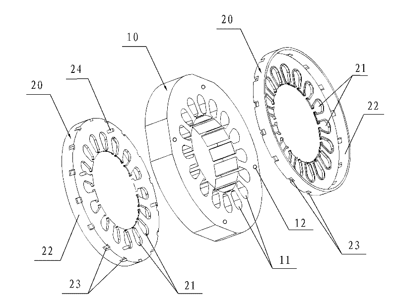
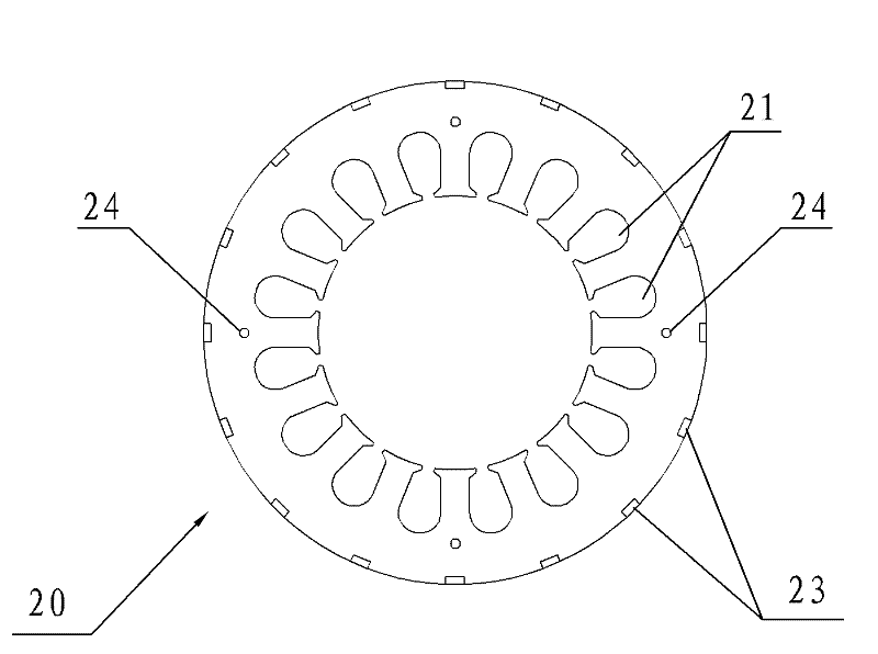
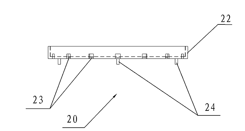
[0014] Such as Figure 1-3 As shown, the squirrel-cage motor stator of the present invention includes a stator core 10 with a plurality of slots 11, and the axial end faces of the stator core 10 are all provided with insulating frames 20 made of insulating materials. The frame 20 is provided with a through hole 21 matched with the slot 11 of the stator core 10 .
[0015] A round edge 22 is provided on the outer circumference of the insulating frame 20 . The round edge 22 can cover the coil on the axial end surface of the insulating frame 20 to prevent the coil from being damaged after being collided.
[0016] A plurality of binding holes 23 are evenly distributed on the round edge 22 . The function of the wire binding hole 23 is to facilitate the binding of the multi-turn coils protruding from the through hole 21 of the insulating frame. Multi-turn coils can be bo...
PUM
 Abstract
Description
Claims
Application Information
 - R&D Engineer
- R&D Manager
- IP Professional
- Industry Leading Data Capabilities
- Powerful AI technology
- Patent DNA Extraction
Browse by: Latest US Patents, China's latest patents, Technical Efficacy Thesaurus, Application Domain, Technology Topic, Popular Technical Reports.
© 2024 PatSnap. All rights reserved.Legal|Privacy policy|Modern Slavery Act Transparency Statement|Sitemap|About US| Contact US: help@patsnap.com