Double-ring network system, method for determining transmission priority in double-ring network and transmission station device

A double-ring network and transmission station technology, applied in the direction of ring network, transmission system, digital transmission system, etc., can solve the problems of transmission time change and time required

Active Publication Date: 2012-07-04
KK TOSHIBA
View PDF7 Cites 0 Cited by
  • Summary
  • Abstract
  • Description
  • Claims
  • Application Information

AI Technical Summary

Problems solved by technology

[0007] For example, there are technical problems in the case of connecting transmission stations with node numbers in the order of the preset transmission order in a ring, and in the case of connecting the transmission stations in a ring regardless of the preset transmission order. , the transmission time required for the synchronization period of the synchronization frame varies greatly
Therefore, for example, in the case of adding 256 transmission stations (including the parent station), the parent station needs 256 scans of the SYN frame, so it takes time for all nodes to send the REQ frame to the parent station

Method used


Image

  • Double-ring network system, method for determining transmission priority in double-ring network and transmission station device
  • Double-ring network system, method for determining transmission priority in double-ring network and transmission station device
  • Double-ring network system, method for determining transmission priority in double-ring network and transmission station device

Examples


Embodiment approach 1

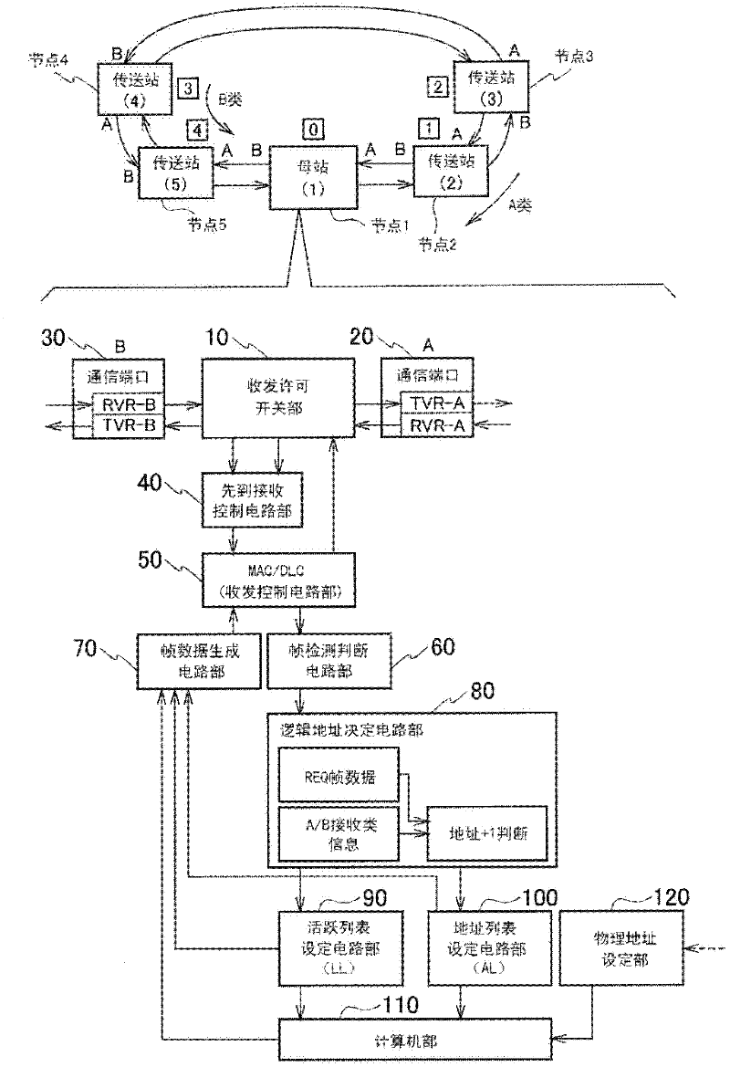
[0046] figure 1 It is a schematic configuration diagram of the control method of the double-ring network according to the first embodiment. The dual-ring network in Embodiment 1 is preferably a network in which two or more transmission stations capable of bidirectional communication are added, two adjacent transmission stations are terminal stations, and a certain transmission station is a parent station.

[0047] Each of the above-mentioned transmission stations has the same configuration as that of the parent station. Furthermore, there is a mechanism for holding the transmission order (logical address) of the own node notified from the parent station, and transmitting transmission frames (including connection request frame, complete frame, etc.) from the own node based on the transmission order.

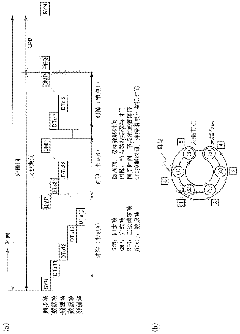
[0048] Generally, in the data transmission method of Patent Document 1, such as figure 2 As shown in (a), at the synchronization time, the tokens are sequenced in the order of ...

Embodiment approach 2

[0138] Figure 20 It is a schematic configuration diagram of a dual-ring network system according to the second embodiment. Embodiment 2 is an example in which a transfer station hub i is inserted into a loop, and a plurality of substations i are connected (star-connected) to the transfer station hub i. exist Figure 20 In FIG. 1 , the transfer station hub 2 is inserted between the transfer station node 5 and the transfer station node 4 , and the transfer station hub 1 is inserted between the transfer station node 2 and the transfer station node 3 . The substation node 1 and the substation node 2 are connected in a star form to the transfer station hub 1 . In addition, the substation node 3 and the substation node 4 are connected to the transfer station hub 2 in a star shape. In such a connection, the master station 1 has the same figure 1 same structure.

[0139] Below, use Figure 22 The case where a hub joins will be described. Also, in the case where transfer statio...


PUM


Abstract

The invention provides a double-ring network system, a method for determining a transmission priority in the double-ring network, and a transmission station device, wherein a transmission time is automatically reduced even if a transmission station is changed or added. In a double-ring network, a master station includes a transmitting and receiving permission switch portion, a communication port A at an A-system side, a communication port B at a B-system side, a first receiving control circuit portion, a transmitting and receiving control circuit portion, a frame detection determining circuit portion, a frame data generating circuit portion, a logical address determining circuit portion, a live list setting circuit portion and an address list setting circuit portion. The master station determines a token order (a transmission priority, also called a logical address) using a shortest path function by the logical address determining circuit portion and the address list setting circuit portion such that the token order does not depend on physical addresses of transmission stations and is matched to a connection order of transmission stations to realize path optimization. This reduces a transmission time.

Description

[0001] This application is based on Japanese Patent Application No. 2010-293159 (filing date: December 28, 2010), and priority is claimed from this application. This application incorporates the entire contents of this application by referring to this application. technical field [0002] Embodiments of the present invention relate to a dual-ring network system, a transmission order determination method of the dual-ring network, and a transmission station device. Background technique [0003] There is a token ring method (hereinafter simply referred to as a token ring) in which data is transmitted and received between a plurality of nodes (also referred to as transmission stations) connected to a transmission path such as a LAN (Local Area Network). In general, in a token ring, tokens are defined so that they always circle the transmission path, and collisions between frames do not occur on the transmission path. That is, unlike the CSMA / CD method, collisions can be avoided...

Claims


Application Information

Patent Timeline
Patent Type & Authority Applications(China)
IPC IPC(8): H04L12/42
CPCH04L41/12H04L12/42H04L12/43H04L12/437
Inventor 冈部基彦河野慎哉柴田浩司
Owner KK TOSHIBA
Why Eureka
Try Eureka